Transform, Segment, and Export 3D Assets Using Asset Generator
R2026bThis example shows how to apply spatial transformations, segment meshes into parts, and export 3D assets using the Asset Generator app. The app simplifies the workflow from creating raw 3D assets to generate simulation-ready 3D asset model within a single environment.
For information on how to generate, import, and visualize 3D assets in the AssetGenerator app, see the Generate and Visualize 3D Assets Using Asset Generator example.
After generating or importing 3D assets, preparing them for simulation often requires spatial adjustments, part decomposition, and format conversion tasks. The Asset Generator app provides an interactive canvas for scaling, rotating, and translating meshes, segmenting them into semantically meaningful parts, and exporting to standard 3D formats or the MATLAB® workspace.
Open App and Load Mesh
To open the Asset Generator app, in the MATLAB command prompt, enter this command.
assetGenerator
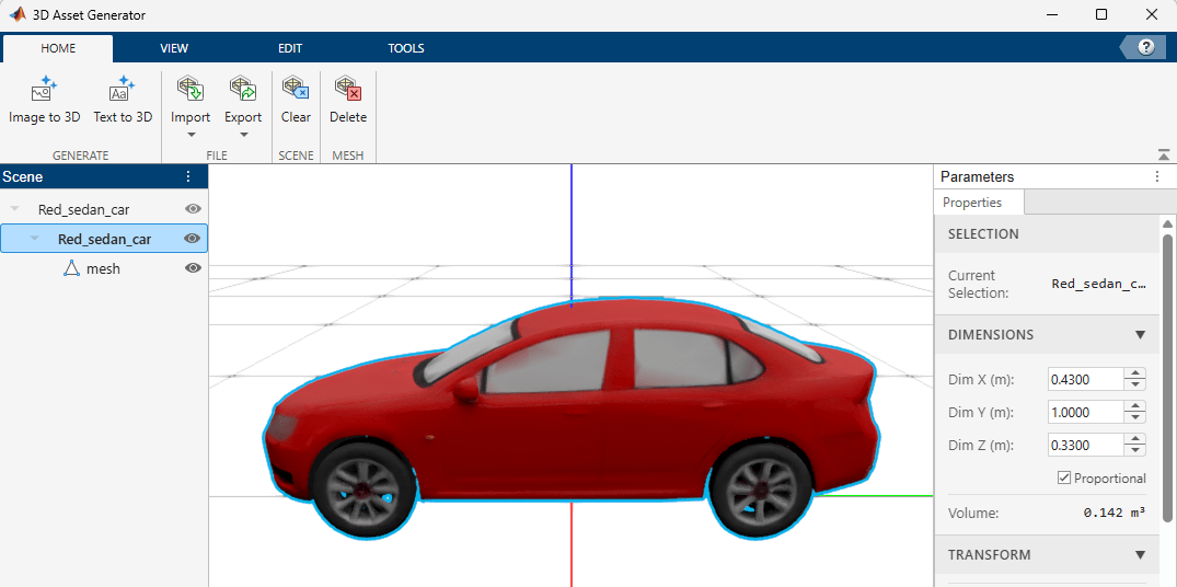
On the Home tab, click Import, select Import from File, and select Red_sedan_car.glb, attached to this example as a supporting file.
Apply Spatial Transformations
Use the Edit tab to apply spatial transformations to selected meshes.
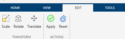
Select the Edit tab on the toolstrip to access these transform modes:
Scale — Resize the mesh uniformly or along individual axes.
Rotate — Rotate the mesh around a specified axis.
Translate — Move the mesh to a new position.
Scale Mesh
Select the mesh in the Scene panel. On the Edit tab, click Scale. The canvas displays a scale handles on the mesh. Drag the handles to resize, or specify dimension values in the Properties panel on the right.
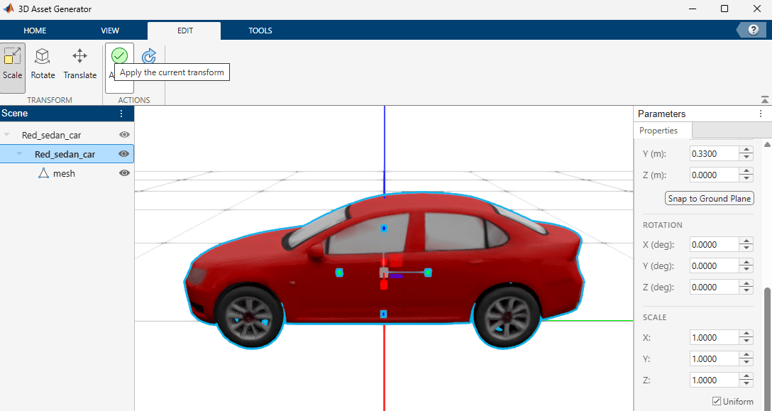
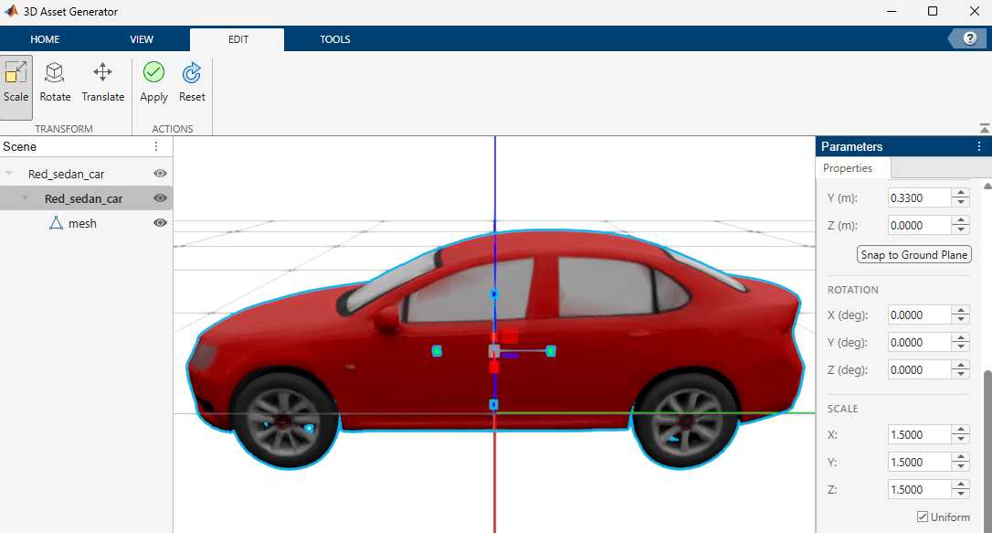
Enable Uniform Scale in the Properties panel to lock all axes to the same scale factor. Changing one axis automatically adjusts the others to preserve the mesh aspect ratio.
For this example, enable Uniform scale and set the scale factor to 1.5.
Rotate Mesh
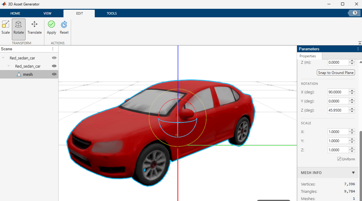
On the Edit tab, click Rotate. The canvas displays rotation rings around the mesh. Drag the rings to rotate, or enter exact angles in the Properties panel.
Translate Mesh
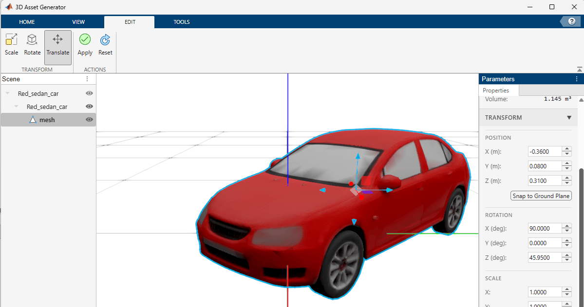
On the Edit tab, click Translate. The canvas displays translation arrows. Drag the arrows to move the mesh, or enter exact position values in the Properties panel.
Apply or Reset Transforms
After adjusting the transform:
Click Apply to bake the transform into the mesh vertex positions.
Click Reset to revert to original values.
Use Snap to Ground Plane to align the mesh bottom to the ground plane. This is especially useful after scaling, as the mesh center may shift and leave the mesh floating above or intersecting the ground.
Use various preset camera views such as isometric, front, side on the View tab to verify transformations from multiple angles before applying.
For this example, click Reset to reset the transformation.
Segment Mesh into Parts
Segment a mesh into semantically meaningful parts based on shape thickness using the Tools tab.
Select the mesh in the Scene panel. On the Tools tab, click Segment. The segmentation panel provides these options:
Number of Components (2-20) — Number of thickness-based groups. The final segment count may exceed this value because spatially disconnected regions become separate segments.
Smoothness Weight (1-50) — Controls segment boundary smoothness. Higher values produce cleaner boundaries.
Smoothing Iterations (1-5) — Number of refinement passes.
Min Component Size (0-500) — Minimum number of faces per segment. Smaller segments merge into neighbors.
For this example, use the default options and click Segment Mesh.
After segmentation completes, the app colors each segment differently.
Note: The number of components specifies the number of thickness-based clusters in the mesh, which is different than the number of segments the app produces.
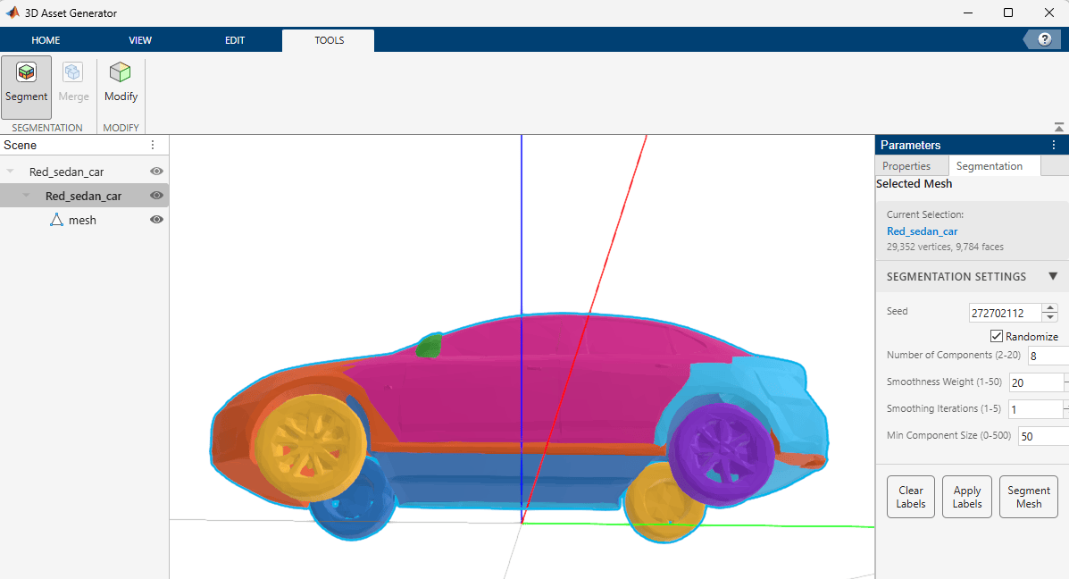
When you click Apply Labels, the Scene panel updates to show segments as sub-meshes. You can label each sub-mesh in the Scene panel by double-clicking the default sub-mesh names.
Alternatively, after segmenting the mesh, you can also click on the colored segments in the canvas that opens a pop-up to name the segments. Name each segment, then click Apply Labels, the Scene panel updates to show segments as sub-meshes with the names you specify.
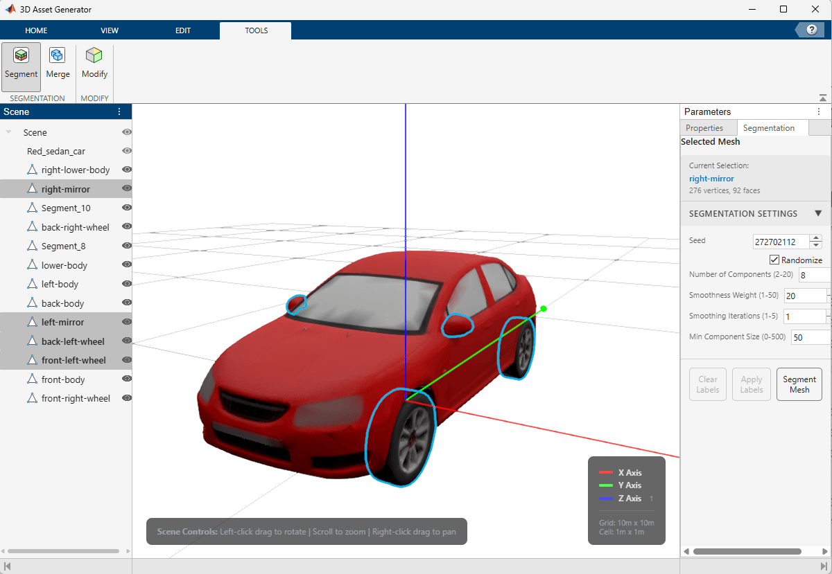
To merge segments back into a single mesh, select multiple segments in the Scene panel (hold Ctrl and click), then on the Tools tab, click Merge.
Modify Mesh Using Generative AI
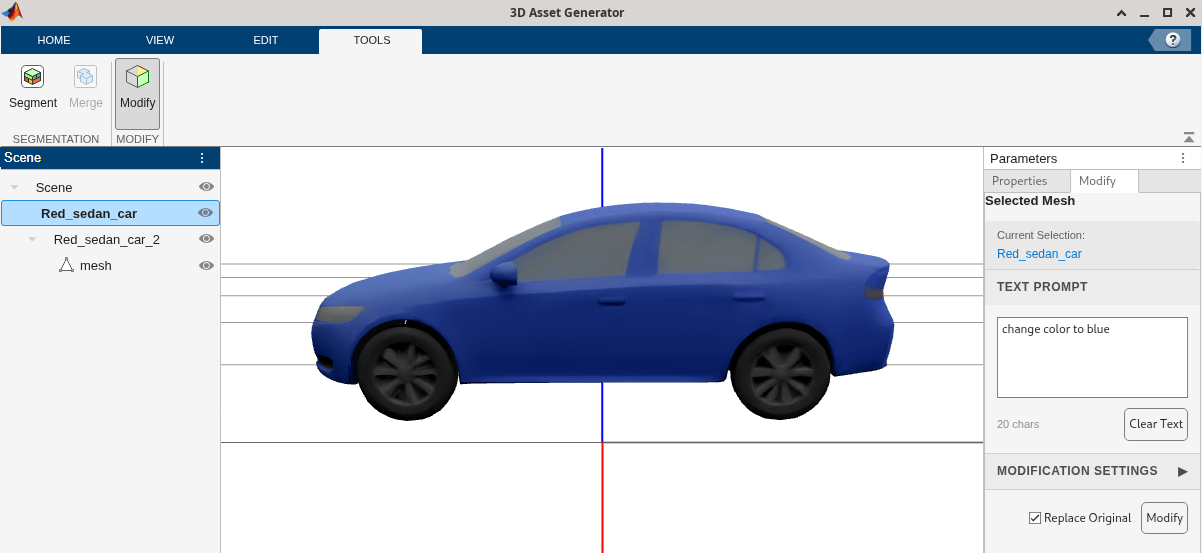
Use the Modify tool on the Tools tab to modify an existing mesh using a text prompt. This workflow requires the Trellis AI server to be running. Select a mesh in the Scene panel. On the Tools tab, click Modify. The modification panel provides:
Text Prompt — Natural language description of the desired modification.
Guidance Strength — Controls how strongly the modification follows the prompt.
Sampling Steps — Number of steps for the modification process.
Texture Size — Resolution of the regenerated texture.
Seed — Random seed for reproducibility.
Enter a text prompt such as "change color to blue", enable Replace Original option, and click Modify to apply AI-based modifications to the selected mesh.
Note: If you modify an asset after segmentation, the app looses the prior segmentation results.
Export 3D Assets
After processing 3D assets, export them to standard file formats or to the MATLAB workspace.
Export to File
Select the mesh in the Scene panel. On the Home tab, click Export. The app supports exporting to these formats:
glTF/GLB (
.gltf,.glb) — Efficient format with full PBR material support.FBX (
.fbx) — Widely supported format for game engines and simulation tools.OBJ (
.obj) — Universal format for geometry exchange.STL (
.stl) — Common format for 3D printing and CAD.PLY (
.ply) — Point cloud and mesh format.USD/USDA/USDC/USDZ (
.usd,.usda,.usdc,.usdz) — Pixar Universal Scene Description formats.Collada (
.dae) — XML-based exchange format.OFF (
.off) — Object File Format for simple geometry.3MF (
.3mf) — 3D Manufacturing Format for 3D printing and manufacturing.URDF (
.urdf) — Robot model description format.
Export to MATLAB Workspace
On the Home tab, click Export and select Export To Workspace. The app creates a Mesh or Scene object in the MATLAB workspace.
Clear and Delete Meshes
To remove individual meshes from the scene, select a mesh in the Scene panel and on the Home tab, click Delete. To remove all meshes, click Clear.

