Update Timer Period and Measure Encoder Counts on Renesas RA Microcontrollers
R2026bThis example shows how to use timer blocks in the Embedded Coder® Support Package for Renesas RA Microcontrollers to dynamically update the timer period, enable or disable the timer during execution, and reset the timer counter by using the AGT peripheral. It also shows how to update the timer period for the GPT peripheral and observe the counter waveform behavior when period values change at different time instants. Additionally, the example demonstrates how to perform phase counting using an encoder. In this example, you emulate the encoder pulses using two phase-shifted GPIO pulses with the GPT peripheral.
Prerequisites
Before you begin,
Complete these tutorials:
Review the MCK-RA6T2 User's Manual.
Complete the Hardware Setup for Embedded Coder Support Package for Renesas RA Microcontrollers.
Required Hardware
Supported Renesas RA hardware board
USB cable
Jumper wires
FTDI-to-USB adapter (required for External mode communication)
Hardware Connection
Connect the jumper wires:
PB06 (GTIOC1A) → PB08
PB07 (GTIOC1B) → PB09
When using an FTDI adapter for communication between the host computer and the Renesas RA6T2 target board, make the following connections.
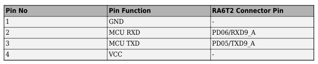
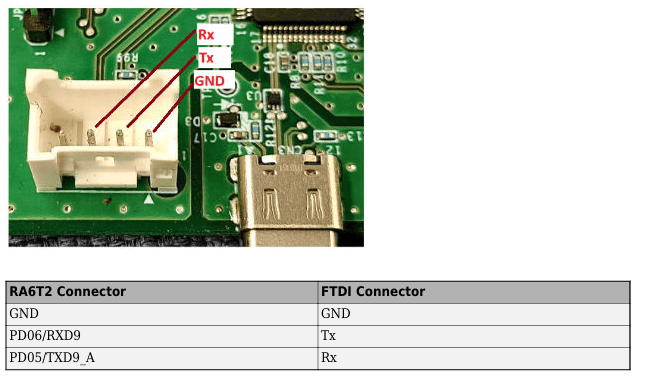
The Rx, Tx, and GND labels shown in red in the figure indicate the corresponding pins on the FTDI connector.
RASC Project File
This example uses a Renesas Smart Configurator (RASC) project file to define the hardware and peripheral configuration required for timer period control and encoder counting.
The RASC project file configures the following components:
Target hardware: RA6T2 microcontroller on the RA6T2-MCK board (Cortex®-M33 core)
AGT timer configuration (g_timer1)
Configured in periodic mode
Used to update timer period and control enable/disable during runtime
GPT timer configuration (g_timer2)
Configured in quadrature encoder mode using GTIOC inputs
Quadrature setting – 4× counting mode enabled to count on every edge of both input signals
Pin configuration
PB06 (GTIOC1A) and PB07 (GTIOC1B) used as GPT inputs
PB08 and PB09 used to generate input signals
Peripheral drivers
AGT – timer period control
GPT – encoder counting
IOPORT – pin configuration
UART – external mode (optional)
Model Overview
This example uses two Simulink® models:
TimerPeriodSet.slx— Demonstrates dynamically updating the GPT timer period during execution by using a stair-step input signal.TimerEnableDisable.slx— Demonstrates timer period update, enable/disable control, and counter reset.TimerEncoder.slx— Demonstrates encoder counting using two phase-shifted input signals.
Run the GPT Timer Period Set Simulink Model
This model demonstrates how to:
Update the GPT timer period during execution
Observe when the updated period takes effect
Compare GPT period update behavior with AGT period update behavior
The model uses three Step blocks connected to a Sum block to generate a stair-step signal that drives the Period(seconds) input of the GPT Timer block configured as g_timer0. The resulting period values are:
1 second for t <
1.5 s2 seconds for
1.5 s≤ t <5 s4 seconds for t ≥
5 s
The summed signal is converted to uint16 before being applied to the GPT Timer block.
1. Open the TimerEnableDisable.slx Simulink model.
modelName = "TimerPeriodSet";
open_system(modelName) 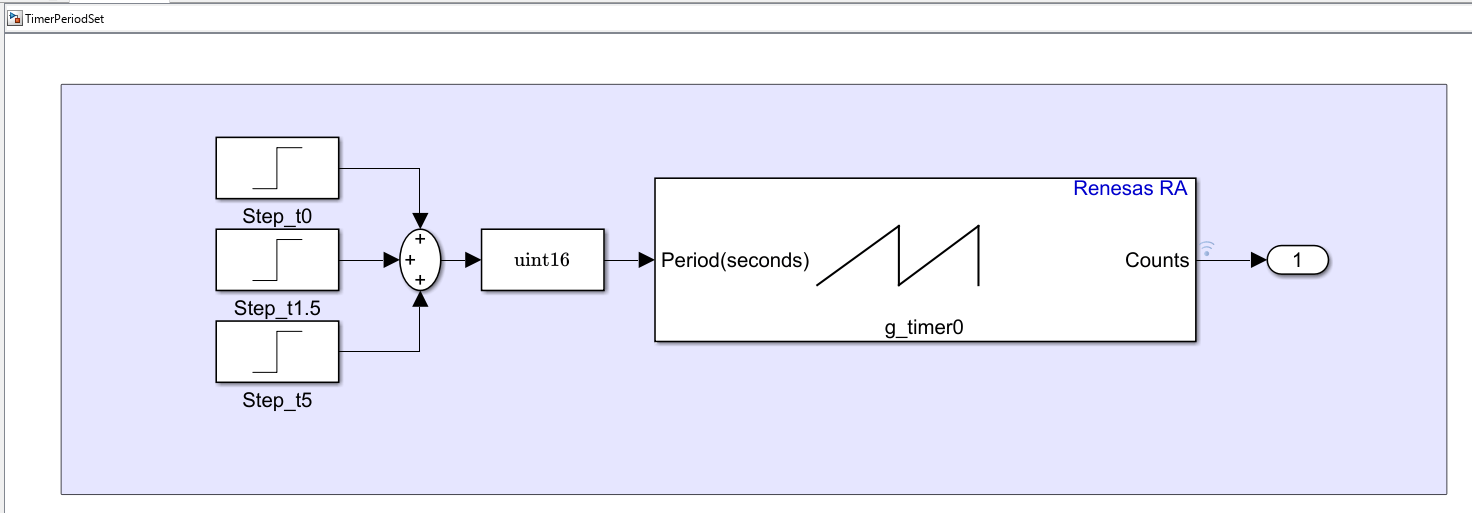
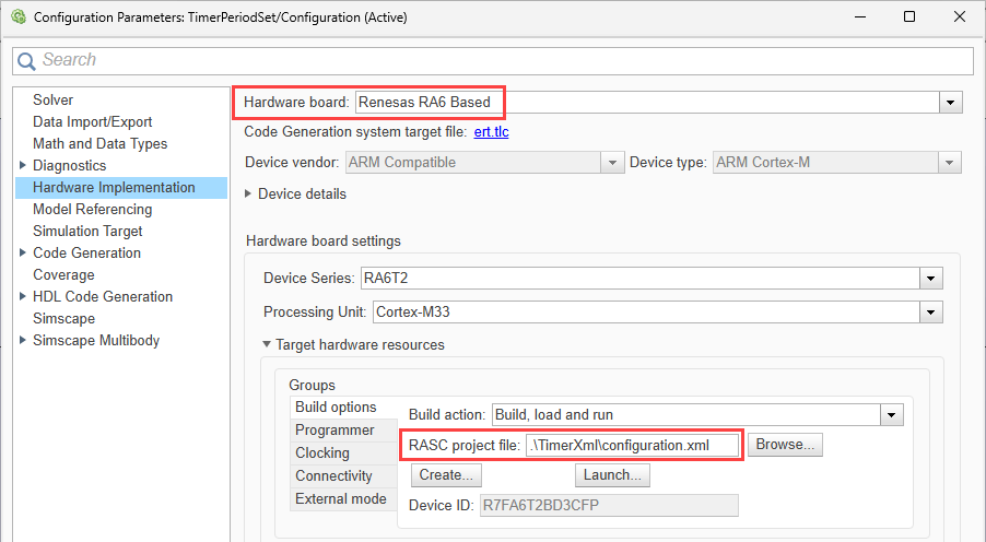
The model is pre-configured for Renesas RA6 Based hardware.
2. Verify the following settings are applied:
configuration.xmlis added as the Renesas Smart Configurator (RASC) project file in Build options. To verify click Modeling > Model Settings to open the Configuration Parameters dialog box. Navigate to Hardware Implementation > Target hardware resources > Build options.
3. Run the model in External mode.
In the Simulink model, click Hardware tab and then click Monitor & Tune.

Results
Observe the timer count output while the application is running.
The timer starts with a period of
1second.At approximately t =
1.5s, the period changes from 1 second to2seconds.At approximately t =
5s, the period changes from2seconds to4seconds.The counter continues running while using the updated timer period values.
The waveform shows how changing the timer period affects the timing of timer overflow events and the resulting counter behavior.
Note: When the timer period update and count read operations occur in the same execution step, the count output can remain constant. This behavior is expected because the timer period is updated each time the block executes. To observe the count ramp behavior, use another Timer block running at a slower sample rate to read the count value.
Run the Timer Period Control Simulink Model
This model demonstrates how to:
Change the GPT timer period during execution.
Enable and disable a GPT timer during runtime.
Observe timer count behavior when the timer state changes.
The model contains two GPT Timer blocks configured as g_timer1.
Timer Period Control
The upper portion of the model drives the Period(seconds) input of the GPT Timer block using two Step signals.The generated period values are:
2seconds for t <4 s3seconds for t ≥4 s
This demonstrates runtime modification of the timer period.
Timer Enable/Disable Control
The lower portion of the model controls the Enable input of the GPT Timer block.Two Step signals and a Product block create an enable window that:
Enables the timer at t =
1sDisables the timer at t =
8.5s
The timer runs only during this interval.
1. Open the TimerEnableDisable.slx Simulink model.
modelName = "TimerEnableDisable";
open_system(modelName) 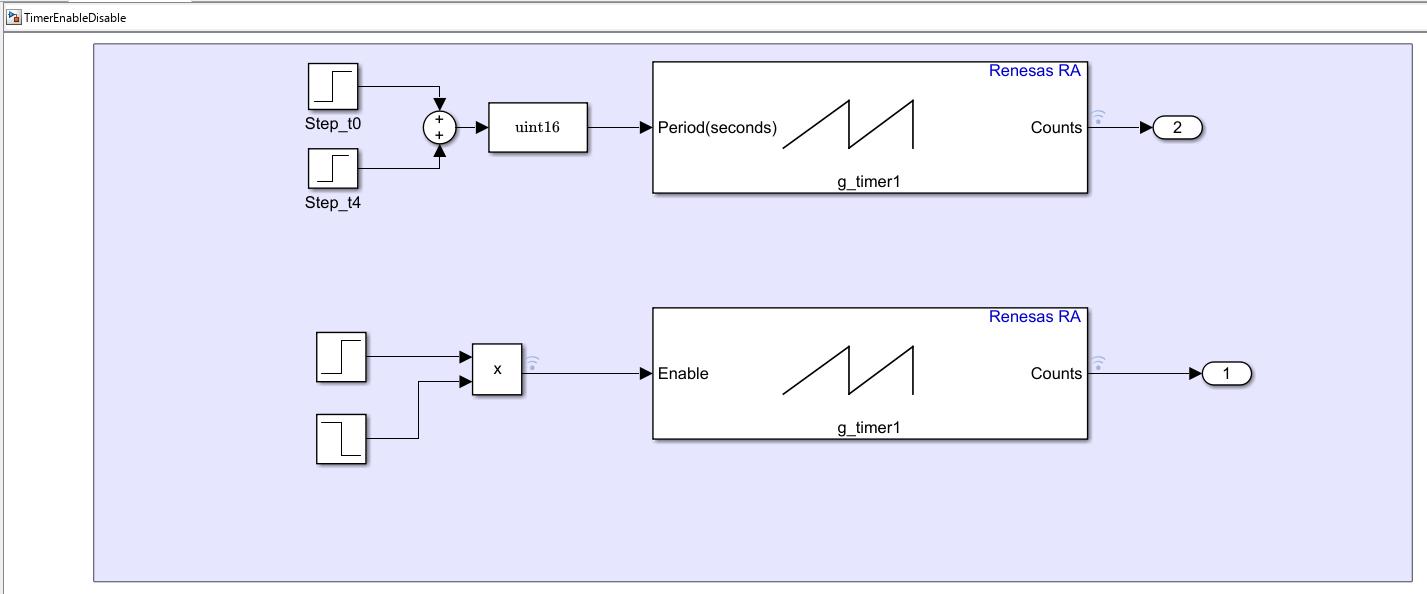
The model is pre-configured for Renesas RA6 Based hardware.
2. Ensure the following settings are applied:
configuration.xmlis added as the Renesas Smart Configurator (RASC) project file in Build options. To verify click Modeling > Model Settings to open the Configuration Parameters dialog box. Navigate to Hardware Implementation > Target hardware resources > Build options.
The example model has these default signal values:
Initial period =
2secondsEnable signal =
0Reset signal =
0
3. Run the model in External mode.
In the Simulink model, click Hardware tab and then click Monitor & Tune.
Results
Use the output waveform to identify these control actions:
The timer is enabled at approximately
t = 1 sand counting begins.The period is updated at approximately
t = 4 s.A reset signal is applied at approximately t = 5 s, causing the counter to restart.
The timer is disabled at approximately
t = 8.5 s, and counting stops.A later period update shows how the counter behavior changes after the timer state changes.
Run the Encoder Counting Simulink Model
This model demonstrates how to:
Perform phase counting using two input signals
Measure encoder counts using a GPT timer
1. Open the TimerEncoder.slx Simulink model.
modelName = "TimerEncoder";
open_system(modelName) 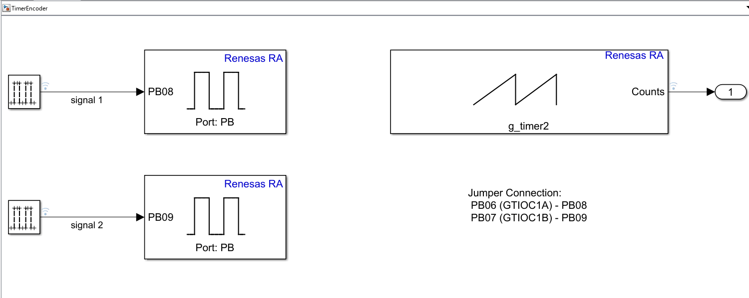
The model is pre-configured for Renesas RA6 Based hardware.
2. Ensure the following settings are applied:
configuration.xmlis added as the Renesas Smart Configurator (RASC) project file in Build options. To verify click Modeling > Model Settings to open the Configuration Parameters dialog box. Navigate to Hardware Implementation > Target hardware resources > Build options.
3. Run the model in External mode.
In the Simulink model, click Hardware tab and then click Monitor & Tune.
Results
Use the waveform to observe how the phase relationship affects the count value:
Two phase-shifted digital signals emulate quadrature encoder outputs.
The GPT timer counts based on transitions on the two input signals.
When one signal leads the other, the counter changes in one direction.
Reversing the phase relationship reverses the counting direction.
If the quadrature setting uses 4× counting, the counter updates on every rising and falling edge of both signals. This lets the GPT peripheral capture more transitions per input cycle and improves count resolution.
Results
Other Things to Try
Change the timer period values in the timer control model and observe how the counter output changes.
Modify the enable duration to control when the timer starts and stops counting.
Adjust the phase difference between signal
1and signal 2 in the encoder model and observe how the count direction changes.

