Getting Started with MCAL DIO Blocks on Renesas RH850 Microcontrollers
This example shows how to control a digital output on a Renesas RH850/U2A16 Microcontroller using the AUTOSAR MCAL DIO Channel Write block in Simulink. The example uses an onboard LED to demonstrate how MCAL DIO configuration and model-based design work together to generate, deploy, and run the model on RH850 hardware to drive an LED.
You can use this workflow to validate basic DIO configuration, confirm toolchain setup, and establish a reusable pattern for controlling digital outputs on RH850 devices.
This example demonstrates two closely related workflows for driving a digital output:
Single Rate LED blinking — Drive an LED at a constant, predefined rate.
Variable Rate LED blinking — Adjust the blink rate by changing the input signal characteristics.
Prerequisites
Before you begin,
Complete these tutorials:
Complete the Hardware Setup for Embedded Coder Support Package for Renesas RH850 Microcontrollers.
Required Hardware
RH850/U2A16 starter kit
Renesas E2 emulator
PC connection cable (USB Type-C)
Hardware Connections
Onboard LED7 is used for the example (No external connections required).
Third-Party Configuration Tool
This example uses a third-party AUTOSAR configuration tool to configure the MCAL modules Port and DIO.
MCAL Configuration Overview
The MCAL configuration for this example is stored in the configuration description file R7F702300x_dio.arxml.
DIO Module Configuration
The DIO module defines logical DIO channels and their mapping to hardware pins.
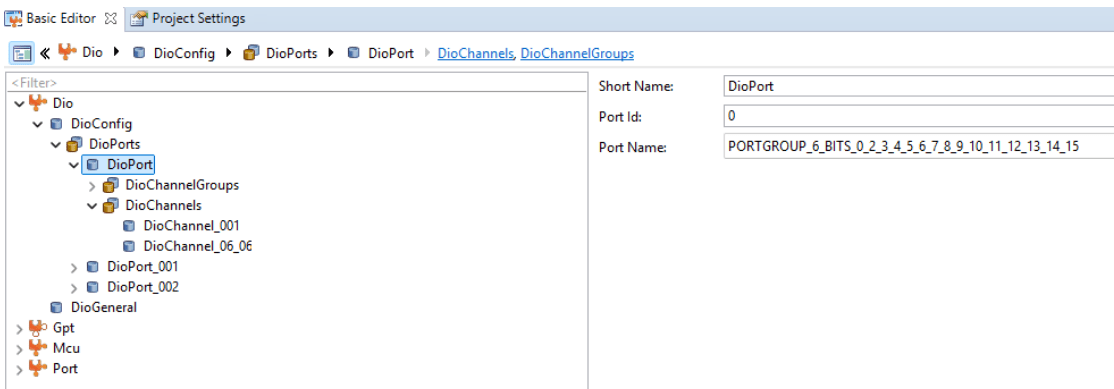
A DioPort group is configured for PortGroup6
A DIO channel with the short name DioChannel_06_06 is defined
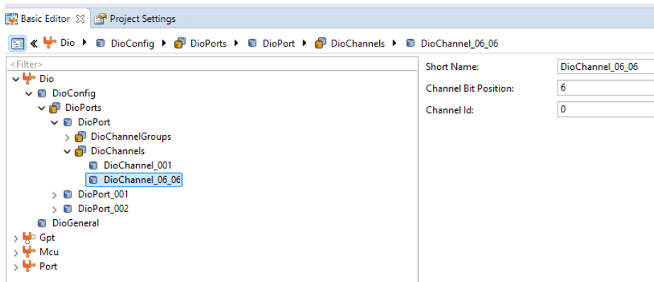
The channel is assigned a bit position of 6, corresponding to pin 6 of Port Group 6. This channel represents the logical output that the Simulink model controls.

A DIO channel with the short name DioChannel_02_03 is defined.
Port Module Configuration
The Port module defines pin-level behavior.
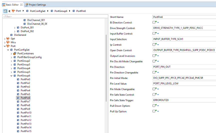
PortPin6 of PortGroup6 is configured.
Pin initial mode is set to
Dio.Port Pin direction is set to output.
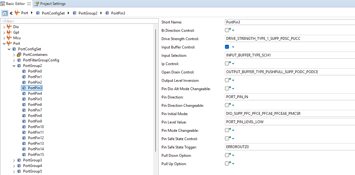
PortPin3 of PortGroup2 is configured.
Pin initial mode is set to
Dio.Port Pin direction is set to input.
This configuration ensures the pin can be driven by the DIO module at runtime.
Configuration Description File
The configuration description file provides the connection between the AUTOSAR MCAL configuration and the Simulink model.
The file R7F702300x_dio.arxml contains the Port and DIO configuration generated by the third-party tool. During build, the model reads this file to resolve DIO channel names and generate hardware-specific code.
Blink LED7 at a Single Rate
Note: On the RH850/U2A16 starter kit, the digital pin P6_6 is connected to LED7. Ensure that switch SW23-2 is set to ON to enable the user signal LEDs.
Open the RH850U2AGettingStarted Simulink model.
modelName = "RH850U2AGettingStarted";
open_system(modelName) 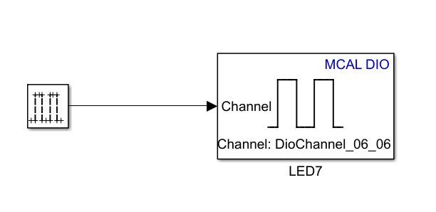
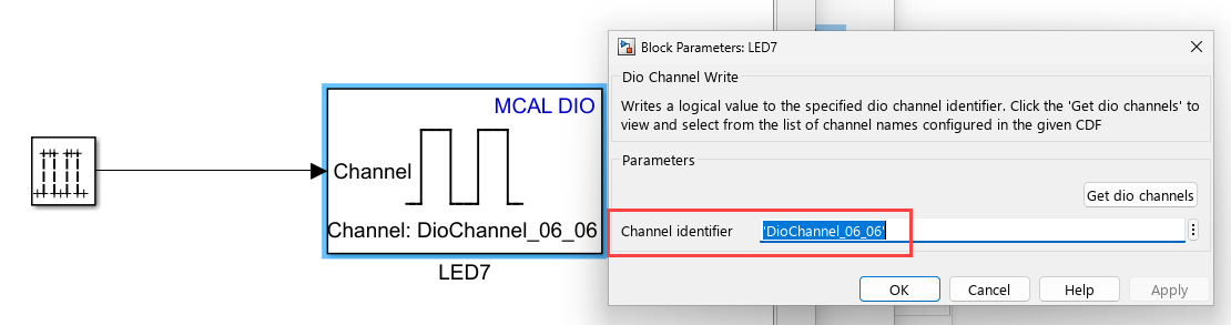
A Pulse Generator block produces a square-wave signal with a 0.5-second positive pulse followed by a 0.5-second negative pulse. This signal is connected to the MCAL Dio Channel Write block.
The channel identifier is set to DioChannel_06_06, as defined in the configuration description file
This channel maps to pin 6 of Port Group 6, which is physically connected to LED7 on the starter kit
As a result, LED7 blinks with a period of 1 second (0.5 seconds ON and 0.5 seconds OFF), following the output of the pulse generator.
Configure the model
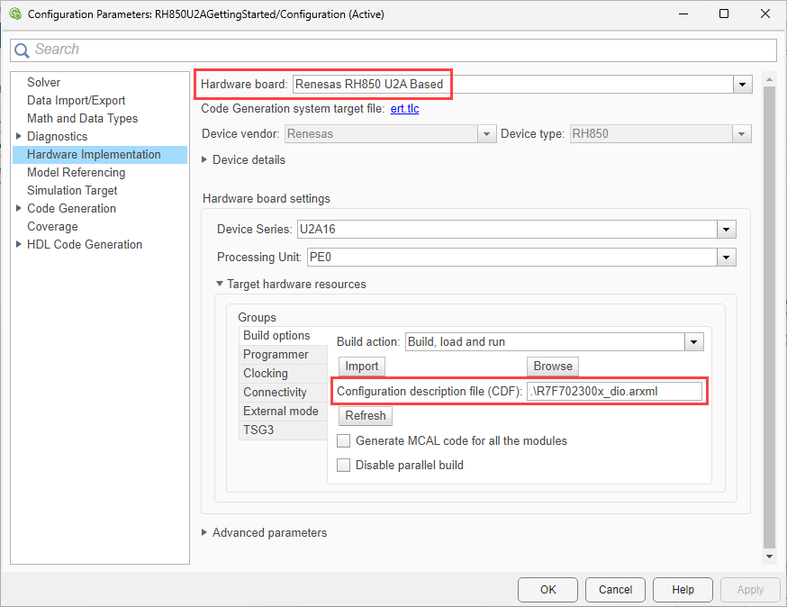
The model is pre-configured for Renesas RH850 U2A Based hardware.
Ensure the following settings are applied:
R7F702300x_dio.arxmlis added as the configuration description file in Build options. To verify click Modeling > Model Settings to open the Configuration Parameters dialog box. Navigate to Hardware Implementation > Target hardware resources > Build options.
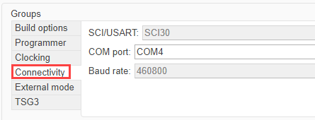
The correct COM port is specified under Hardware Implementation > Target hardware resources > Connectivity as shown in this image.
Configure the Blocks
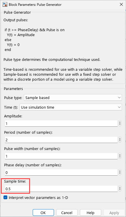
Double click the Pulse Generator block to open the block parameters dialog.
Pulse generator is configured with sample time 0.5 second.
The DIOChannel Write block uses 'DioChannel_06_06', which is configured in the CDF, as the Channel identifier.
Run Model on Hardware
To deploy and run the model:
1. In the Simulink toolstrip, click Hardware and then click Monitor & Tune.

2. Observe LED7 on the RH850/U2A16 starter kit. It blinks a varying rate, as defined in your model.
Successful execution confirms correct Port and DIO configuration and verifies end-to-end DIO control from Simulink to hardware.
Blink LED7 at Varying Rates
Note: On the RH850/U2A16 starter kit, the digital pin P6_6 is connected to LED7. Ensure SW23-2 is set to ON to enable the user signal LEDs, and SW23-1 is set to ON so that SW20 is connected to Port P2_3.
Change the LED blink rate by adjusting the input signal.
You can vary the blink rate by modifying Pulse Generator parameters such as:
Sample time
Pulse width
Period
No changes to the MCAL configuration or DIO block are required. This demonstrates how application-level timing changes propagate directly to hardware outputs.
Open the RH850U2AMultiRateGettingStarted.slx Simulink model.
modelName = "RH850U2AMultiRateGettingStarted";
open_system(modelName) 
Configure the model
The model is pre-configured for Renesas RH850 U2A Based hardware.
Ensure the following settings are applied:
R7F702300x_dio.arxmlis added as the configuration description file in Build options. To verify click Modeling > Model Settings to open the Configuration Parameters dialog box. Navigate to Hardware Implementation > Target hardware resources > Build options.
Configure the Blocks
Double click the Dio Channel Read block to open the block parameters dialog.

The Dio Channel Read block uses 'DioChannel_02_03'.

The MCAL DIO Channel Write block uses 'DioChannel_06_06', which is configured in the CDF, as the Channel identifier.
Run Model on Hardware
To deploy and run the model:
1. In the Simulink toolstrip, click Hardware and then click Monitor & Tune.

2. Observe LED7 on the RH850/U2A16 starter kit. It blinks a varying rate, as defined in your model. Upon successful code deployment, LED7 begins blinking every 100 ms. When the switch (SW20, Port P2_3) is pressed, LED7’s blink rate changes to 500 ms, and on the next press, it changes to 1000 ms.
Successful execution confirms correct Port and DIO configuration and verifies end-to-end DIO control from Simulink to hardware.