Generate Board-Independent HDL IP Core for Xilinx Platforms
This example shows how to generate an HDL IP core for generic Xilinx® platform. You generate an HDL IP core for a model that controls the blinking of an LED light, then integrate this HDL IP core into a target Xilinx platform of your choice.
You can generate a reusable IP core module from a Simulink® model using HDL Coder™. The generated IP core connects to an embedded processor on an FPGA device. HDL Coder generates HDL code from the Simulink® blocks, and also generates HDL code for the AXI interface logic that connects the IP core to the embedded processor. HDL Coder then packages the generated files into a folder you specify. You can then integrate the generated IP core with a larger FPGA embedded design in the Xilinx Vivado® environment.
Prepare Model for IP Core Generation
1. Open the hdlcoder_led_blinking_4bit model and select the led_counter subsystem.
open_system('hdlcoder_led_blinking_4bit');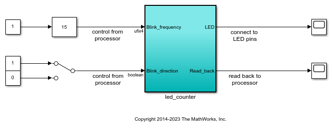
2.Set the path to the Xilinx Vivado SoC synthesis tool by using the hdlsetuptoolpath function:
hdlsetuptoolpath('ToolName','Xilinx Vivado','ToolPath',...
             'C:\Xilinx\Vivado\2023.1\bin\vivado.bat');
See HDL Language Support and Supported Third-Party Tools and Hardware for the latest supported version of the synthesis tool.
3. In the Apps tab, click HDL Coder. In the HDL Code tab, in the Output section, set the drop-down button to IP Core.
4. Select the led_counter subsystem, which is the device under test (DUT) for this example. Ensure that Code for is set to this subsystem. To remember the selection, you can pin this option.
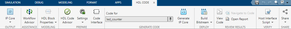
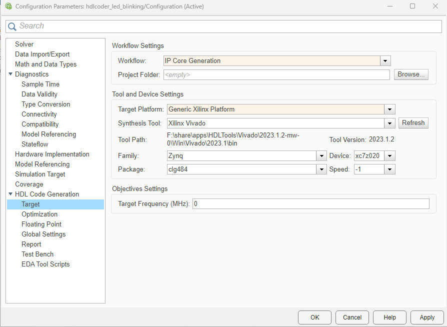
5. Open the HDL Code Generation > Target tab of Configuration Parameters dialog box by clicking the Settings button.
6. Set the Target Platform parameter to Generic Xilinx Platform. Set the Synthesis Tool to Xilinx Vivado.
7. Click OK to save your updated settings.
Configure Design and Target Interface
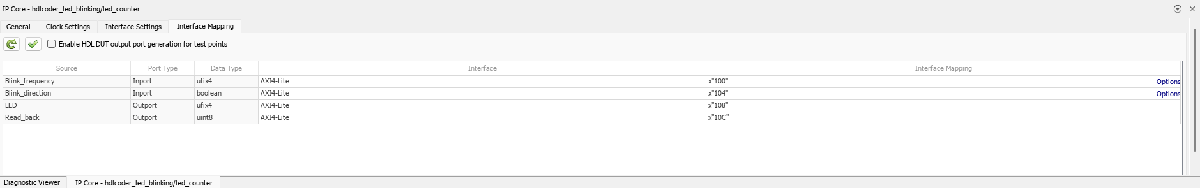
Configure your design to map to the target hardware by mapping the DUT ports to the IP core target hardware and setting the DUT-level IP core options. In this example, all the ports are mapped to the AXI4-Lite interface, so HDL Coder generates AXI interface accessible registers for them.
1. In Simulink, in the HDL Code tab, click Target Interface to open the IP Core editor.
2. To map each DUT prt to one of the IP core target interfaces, select the Interface Mapping tab. The generated design can then communicate with the rest of the hardware system when you deploy it. If no mapping table appears, click the reload IP core settings button ![]() to compile the model and repopulate the DUT ports and their data types.
to compile the model and repopulate the DUT ports and their data types.
3. For the DUT ports Blink_frequency, Blink_direction, LED, Read_back, set the cells in the Interface column to AXI4-Lite.
4. Validate your settings by clicking the Validate IP core settings button ![]() .
.
In the IP Core editor, you can optionally adjust the DUT-level IP core settings for your target hardware by:
Using the General tab to configure top-level settings, such as the name of the IP core and whether to generate an IP core report.
Using the Clock Settings tab to configure clock-related settings.
Using the Interface Settings tab to configure interface-related settings, such as the register interface and FPGA data capture properties.
Generate IP Core
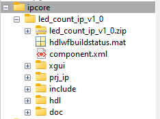
After you configure the IP core settings and mappings for your design, you can generate an IP core. In the Simulink Toolstrip, in the HDL Code tab, click Generate IP Core. After you generate the custom IP core, the IP core files are in the ipcore folder in your current directory. To specify a top-level project folder for the ipcore folder and the other generated files, in the Configuration Parameters dialog box, use the Project Folder parameter in the HDL Code Generation > Target pane. If the Project Folder parameter is empty, HDL Coder saves the generated files in the current directory.
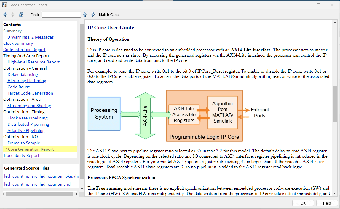
Generating an IP core also generates the code generation report. In the Code Generation Report window, in the left pane, click IP Core Generation Report. The report describes the behavior and contents of the generated custom IP core.
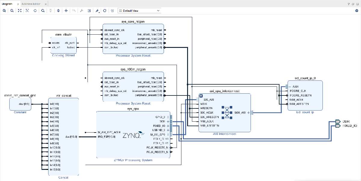
Insert HDL IP Core in Xilinx Vivado SoC Project
To import an IP core generated using HDL Coder into a Xilinx Vivado project:
1. Open a Xilinx Vivado project.
2. Add the IP core folder to the project. In the Project M****anager pane, select IP Catalog.
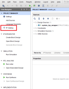
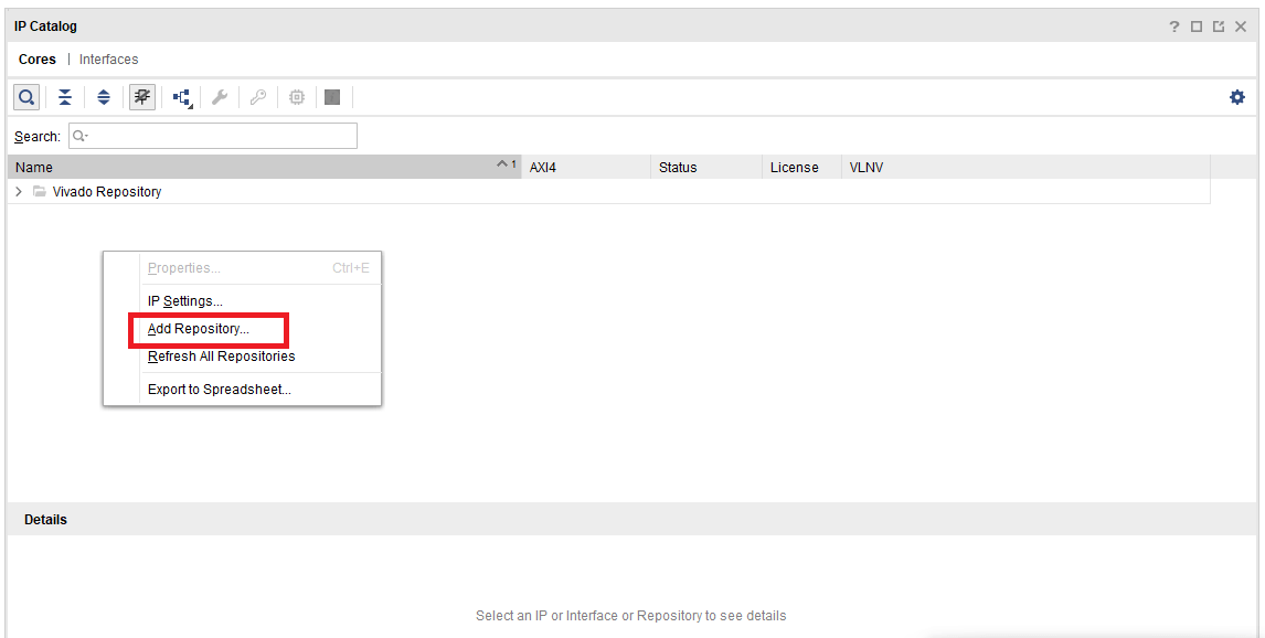
3. Right-click in the IP Catalog pane and select Add Repository.
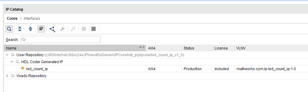
4. Select the folder created by the HDL Workflow Advisor.
5. Open the block diagram. In the Project manager pane, click Open block diagram.

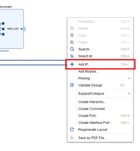
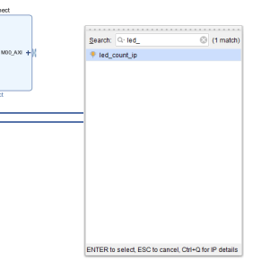
6. To insert the IP generated by HDL Coder generated IP right-click inside the block diagram and select Add IP.
7. Search for the name of the IP and press E****nter.
8. Connect the ports on the IP core block according to your requirements.