Elbow (G)
Libraries:
Simscape /
Fluids /
Gas /
Pipes & Fittings
Description
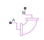
The Elbow (G) block models flow in a pipe turn in a gas network. The block calculates pressure losses due to pipe turns, but omits the effect of viscous friction. The block models losses with hydraulic loss coefficients and the results may be more accurate for lower speed flows where you can neglect compressible flow effects.
You can model a smoothly curved or sharp-edged pipe elbow by setting the
Elbow type parameter to Smoothly
curved or Sharp-edged (Miter),
respectively. To model a smooth pipe with a 90o bend that
models losses due to friction, you can also use the Pipe Bend
(G) block.
Loss Coefficients
When the Elbow type parameter is Smoothly
curved, the block calculates the loss coefficient as:
The block calculates Cangle, the angle correction factor, from Keller [2] as
where θ is the value of the Bend angle parameter in degrees. The block defines the friction factor, fT, as the value for clean commercial steel. The block then interpolates the values from tabular data based on the internal elbow diameter for fT based on Crane [1]. This table contains the pipe friction data for clean commercial steel pipe with flow in the zone of complete turbulence.
| r/d | 1 | 1.5 | 2 | 3 | 4 | 6 | 8 | 10 | 12 | 14 | 16 | 20 | 24 |
|---|---|---|---|---|---|---|---|---|---|---|---|---|---|
| K | 20 fT | 14 fT | 12 fT | 12 fT | 14 fT | 17 fT | 24 fT | 30 fT | 34 fT | 38 fT | 42 fT | 50 fT | 58 fT |
The values provided by Crane are valid for diameters up to 600 millimeters. The friction factor for larger diameters or for wall roughness beyond this range is calculated by nearest-neighbor extrapolation.
When the Elbow type parameter is Sharp-edged
(Miter), the block calculates the loss coefficient
K for the bend angle, α, according to
Crane [1].
| α | 0° | 15° | 30° | 45° | 60° | 75° | 90° |
|---|---|---|---|---|---|---|---|
| K | 2 fT | 4 fT | 8 fT | 15 fT | 25 fT | 40 fT | 60 fT |
Mass Flow Rate
Mass is conserved through the pipe segment
The mass flow rate through the elbow is
where:
A is the flow area.
is the average fluid density.
Δp is the pipe segment pressure difference, pA – pB.
The critical pressure difference, Δpthreshold, is the threshold for transition between laminar and turbulent flow
where:
pA is the pressure at port A.
pB is the pressure at port B.
Blam is the value of the Laminar flow pressure ratio parameter.
Energy Balance
The block balances energy such that
where:
ϕA is the energy flow rate at port A.
ϕB is the energy flow rate at port B.
Ports
Conserving
Parameters
References
[1] Crane Co. Flow of Fluids Through Valves, Fittings, and Pipe: Technical Paper No. 410. Crane Co., 1981.
[2] Keller, G. R. Hydraulic System Analysis. Penton, 1985.
Extended Capabilities
Version History
Introduced in R2023a