Data Center Cooling
This example models the cooling system of a data center. The system consists of two separate water loops: a chilled water loop and a condenser water loop. The chilled water loop absorbs heat from the server farm and transfers it to the condenser water loop. The condenser water loop rejects this heat to the environment using a cooling tower.
The heat transfer between the chilled water loop and condenser water loop occurs directly via the water-water heat exchanger and indirectly via the chiller. The heat exchanger is inexpensive to operate as it does not consume power. However, it must be supplemented by the chiller to provide sufficient cooling to the chilled water loop. The chiller is a refrigeration cycle that consumes power to transfer heat from the evaporator to the condenser via the R-134a refrigerant. It is the largest contributor to the energy consumption of the overall system.
The model includes several variants. The chiller can be modeled directly using the System-Level Refrigeration Cycle (2P) block or abstractly based on pipe heat transfer. Pipe heat transfer is simpler and allows for more efficient simulation. The environmental conditions and the server farm heat load can be variable or constant. Variable conditions and load provide a more realistic scenario. Constant conditions and load allow for simpler component sizing and analyses.
Model

Chiller - Abstract Model Subsystem

Chiller - Refrigeration Cycle Subsystem

Cooling Tower Subsystem

Server Farm Subsystem

Simulation Results from Scopes

Simulation Results from Simscape Logging
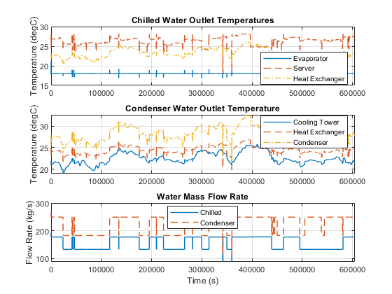
This plot shows the mass flow rates and temperatures of the chilled water loop and the condenser water loop. In the chilled water loop, the chiller's evaporator maintains a temperature of 18 degC. The chilled water absorbs heat from the server farm, transfers part of the heat to the condenser water via the heat exchanger, and transfers the remaining heat to the condenser water via the chiller. The chilled water pump adjusts the flow rate to keep the water temperature at the server outlet at around 28 degC.
In the condenser water loop, the cooling tower cools the water as much as possible based on environmental conditions. The condenser water absorbs heat from the chilled water via the heat exchanger and the chiller, then rejects all heat to the environment via the cooling tower. The condenser water pump adjusts the flow rate to keep the water temperature difference across the heat exchanger and condenser to around 6 degC.
This plot shows the evaporative cooling performance of the cooling tower. The cooling tower removes heat from the condenser water by allowing some of the water to evaporate into the environment. The heat of vaporization needed for evaporation comes from the water and thus it cools the water. The fan draws in fresh air from the environment and pushes out the hot humid air. A colder and dryer environment increases the performance of the cooling tower. Unlike a regular water-air heat exchanger, the cooling tower can reduce the water temperature to below the environment temperature. The drawback is the loss of around 1% of the water flow, which must be replenished.
The evaporative process is modeled approximately using the e-NTU method based on an analogy between heat and mass transfer. For sensible heat transfer, the e-NTU method obtains the heat flow rate by multiplying the theoretical maximum temperature difference with an effectiveness factor. For evaporative heat transfer, the analogous e-NTU method multiplies the theoretical maximum mixture enthalpy difference with an effectiveness factor. The use of mixture enthalpy accounts for differences in both temperature and humidity. The maximum occurs when air is assumed to become fully saturated with the evaporated water.

This plot shows the performance of the chiller and the overall system. The chiller's coefficient of performance (CoP) is the ratio of the heat transfer in the evaporator to the power consumed by the compressor. Applying the same concept to the entire system, the system's CoP is the ratio of the heat transfer in the server farm to the total power consumed by the compressor, fan, and all pumps. Both CoP values are around 13, which is higher than typical air conditioning units. This is because heat transfer between the refrigerant and water is more effective than heat transfer between the refrigerant and air. This allows the refrigeration cycle to have a smaller temperature difference and thus smaller pressure difference between the condenser and evaporator, which reduces the work required by the compressor.

See Also
System-Level Refrigeration Cycle (2P) | Cooling Tower (TL-MA)