Pressure Relief Valve Test Rig
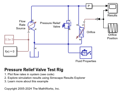
This example shows a test rig to check the pressure-flow characteristic of the Pressure Relief Valve (IL) block. A pressure relief valve and a variable orifice connect to a constant flow rate source in parallel. As the orifice closes, pressure gradually builds up and eventually reaches the set pressure differential of the pressure relief valve. At this pressure, the valve begins to divert flow to the tank and regulates the pressure at the source outlet. As the orifice opens again, the pressure relief valve closes and the entire flow passes through the variable orifice.
Model
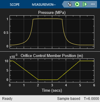
Simulation Results from Scopes
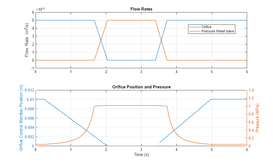
Simulation Results from Simscape Logging
The plots below show the behavior of the pressure relief valve. As the load orifice closes, pressure in the system rises. When the system pressure reaches the pressure setting for the pressure relief valve, the valve opens which diverts flow away from the orifice and allows the system to maintain the set pressure of the pressure relief valve.