Simulate Calculation of Rotor Position Using Quadrature Decoder Block
This example shows how to use the Quadrature Decoder block to extract mechanical position measurements for a PMSM and compensate for offsets when converting the measurements to electrical position. It also explains how to adapt the block for different encoders when you deploy your model to hardware.
For an example involving the same measurements on target hardware, see Field-Oriented Control of PMSM Using Quadrature Encoder.
Workflow for Calculating Rotor Position
When using the Quadrature Decoder block to calculate rotor position, the steps you take depend on the availability of index pulses, encoder driver rollover, and encoder output reset.
Calculate Rotor Position
Use the Quadrature Decoder block to measure rotor mechanical position. For such measurements, an index pulse enables you to wrap the position count to zero after a full revolution. If an index pulse is not available, you can employ other methods, depending on the capabilities of your encoder driver.
Quadrature Decoder with Index Pulse
Open the example model CalculatePositionFromEncoderWithIndex, which simulates the raw uint16 data output (ranging from 0 to 65535) from the encoder. The model assumes the encoder has 1000 slits with four counts per slit, equivalent to 4000 counts per revolution. The driver latches the encoder count output at every 4000 counts (one mechanical rotation) to simulate the behavior of the index pulse.
modelName = 'CalculatePositionFromEncoderWithIndex';
open_system(modelName);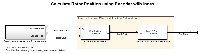
Run the simulation.
sim(modelName);
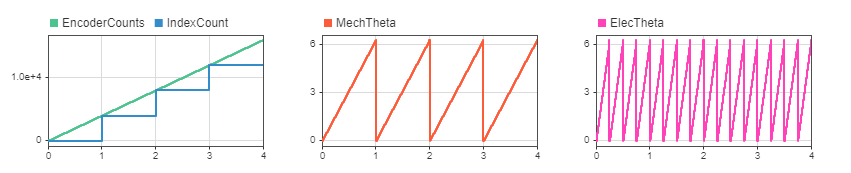
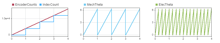
The quadrature decoder subtracts the latched index count from the free running encoder count to obtain a position count in the range [0, counts per revolution]. It then converts the position count to angular position in radians.
Quadrature Decoder Without Index Pulse
If an index pulse is not available, you must use another method to wrap the encoder count output. For example, you can manually program logic to wrap the free running count output. You can also use an encoder driver to roll over the count output at a specific value (such as counts per revolution), provided your driver has this capability.
Free Running Encoder Count Output
Open the example model CalculatePositionFromEncoderWithoutIndexNoRollOver, which simulates the raw uint16 data output (ranging from 0 to 65535) from the encoder. The model assumes the encoder has 1000 slits with four counts per slit, equivalent to 4000 counts per revolution.
modelName = 'CalculatePositionFromEncoderWithoutIndexNoRollOver';
open_system(modelName);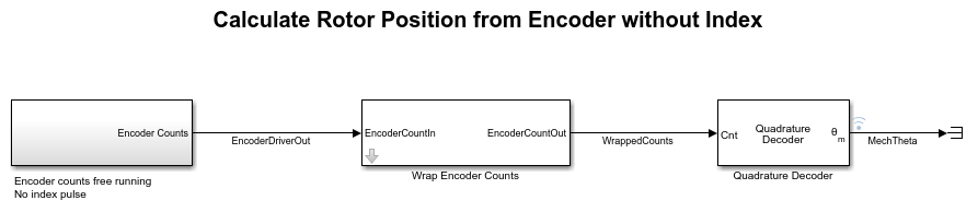
Since no index pulse is available, the same is absent in the simulation. The Quadrature Decoder block requires the encoder count input to be wrapped to counts per revolution. To wrap the count, the model places a Wrap Encoder Counts block between the encoder driver output and the Quadrature Decoder block.
Run the simulation.
sim(modelName);
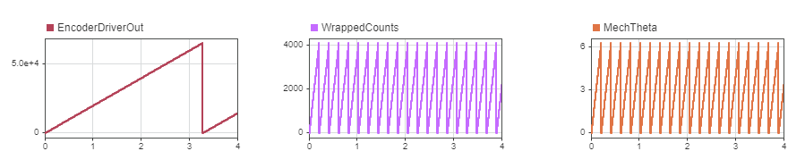
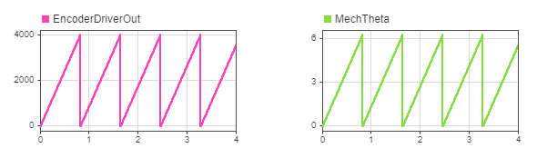
The Wrap Encoder Counts block wraps the free running encoder count to zero when the count exceeds counts per revolution. The quadrature decoder then converts the wrapped count to angular position in radians.
Encoder Driver Count Rollover
Open the example model CalculatePositionFromEncoderWithoutIndexWithRollOver, which simulates a driver that wraps the output to a desired range. In this case, you configure the encoder driver to be wrapped every 4000 counts per revolution.
modelName = 'CalculatePositionFromEncoderWithoutIndexWithRollOver';
open_system(modelName);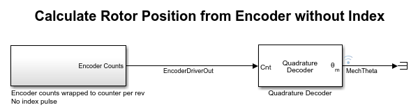
Run the simulation.
sim(modelName);
The driver wraps the output when it exceeds the counts per revolution, then converts the wrapped count to angular position in radians.
Compensate for Offset
To accurately integrate quadrature decoder measurements into the rest of your motor control system, you must compensate for the offset between the measured mechanical position and the rotor electrical position.
Calibrate One Time with Index Pulse
Open the Quadrature Encoder Offset Calibration for PMSM example, which shows how to calibrate the offset between the rotor zero position and the sensor zero position when an index pulse is available. Feed the calibrated offset into the Mechanical to Electrical Position block to compensate for the offset.
Calibrate During Startup When Index Pulse Is Absent
When no index pulse is available, the quadrature encoder does not have an absolute position. Therefore, a fixed offset does not exist between the sensor position and the rotor zero position. In this scenario, you can use either of two approaches to obtain an accurate rotor position.
Capture Offset During Startup and Compensate Later
This approach captures the mechanical position detected when the rotor is aligned to the zero position and uses this position as the offset for the Mechanical to Electrical Position block.
Open the example model CompensateEncoderOffsetWithoutIndex.
modelName = 'CompensateEncoderOffsetWithoutIndex';
open_system(modelName);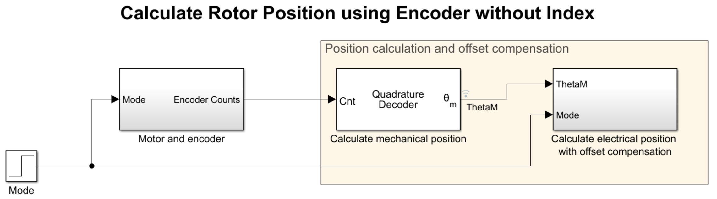
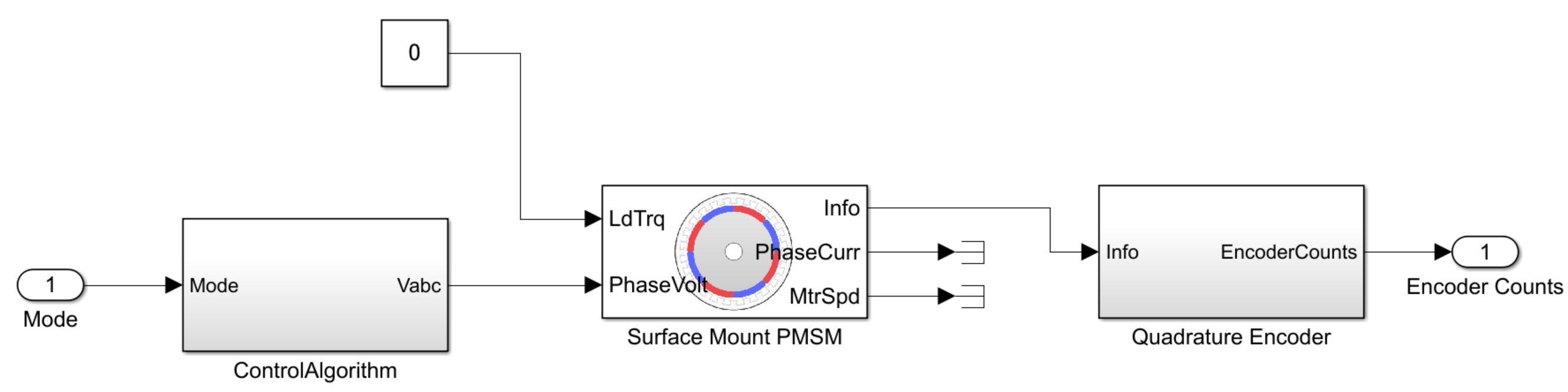
The Motor and encoder subsystem contains a Surface Mount PMSM block that simulates the following two phases.
Rotor alignment (
Mode= 0): The rotor aligns to the zero position. The model captures the mechanical position calculated using the quadrature decoder output.Run (
Mode= 1): The rotor starts spinning. The Mechanical to Electrical Position block uses the captured offset from the previous phase as its offset input.
Run the simulation.
sim(modelName);
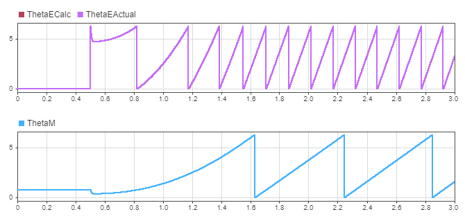
An offset exists between the quadrature decoder mechanical output ThetaM and the surface mount PMSM electrical output ThetaEActual. However, the output of the Mechanical to Electrical Position block ThetaECalc matches ThetaEActual after offset compensation, as suggested by their overlapping graphs.
Reset Encoder Driver Output During Startup
For this approach, you must have an encoder driver capable of resetting the count upon a trigger.
Align the rotor to zero position by exciting the first phase. When you have aligned the rotor, reset the quadrature decoder output to start counting from the zero position. Doing so causes the rotor zero position to align with the encoder zero position.
Swap Motor Without Altering Quadrature Decoder Block
You can efficiently switch to another motor with a different quadrature encoder by passing encoder calibration data as inputs to the Quadrature Decoder block. When you deploy the block to hardware, feed the encoder parameters as input signals by using a communications channel (UART, SPI, CAN, etc.), or read them from calibration data and feed them to the quadrature decoder. Doing so enables you to reuse the code for different encoder hardware without having to regenerate code every time you modify the encoder parameters.
Open the example model CalculatePositionFromEncoderParameterInputs. The model passes the calibration data as inputs to the quadrature decoder.
modelName = 'CalculatePositionFromEncoderParameterInputs';
open_system(modelName);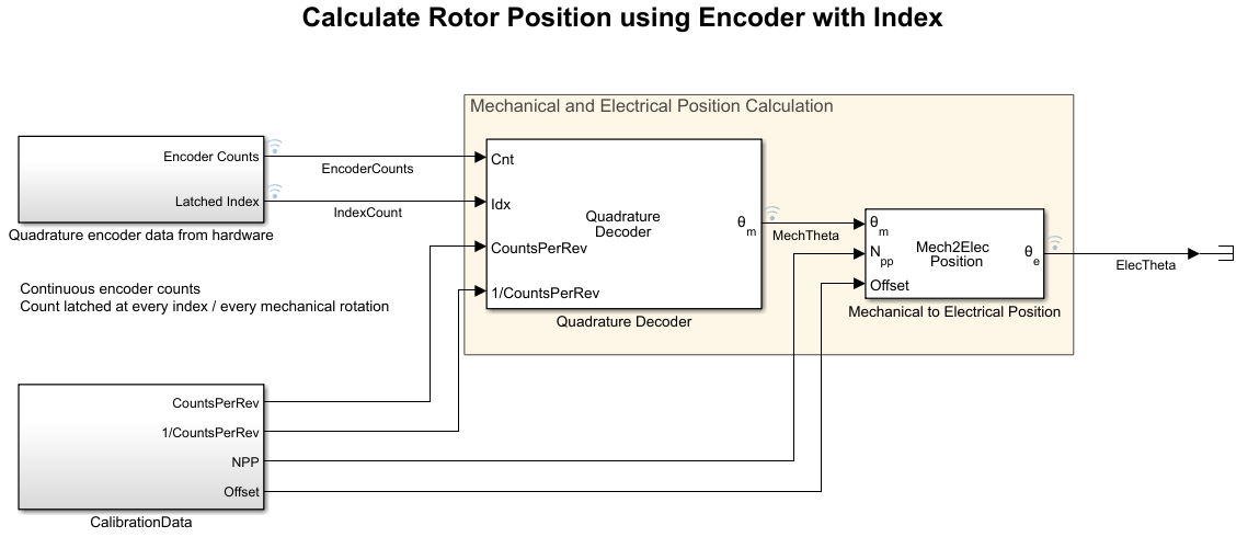
Run the simulation. Since an index pulse is available, you get the same results as in the section Quadrature Decoder with Index Pulse.
sim(modelName);
See Also
Quadrature Decoder | Mechanical to Electrical Position