PMSM HDL
Three-phase permanent magnet synchronous motor with sinusoidal back electromotive force
Since R2022b
Libraries:
Motor Control Blockset HDL Support /
Electrical Systems /
Motors
Description
The PMSM HDL block implements a three-phase permanent magnet synchronous motor (PMSM) with a sinusoidal back-electromotive force. The block uses three-phase input voltages to regulate the individual phase currents, thereby controlling the motor torque or speed.
The block generates code for fixed-step double- and single-precision targets using the Sample Time (s) parameter. It supports code generation for FPGA deployment and generates HDL-compatible code.
You can specify the PMSM parameters and operating mode using the Config input port. You can also use the PMSM Configuration block to generate the required configuration signal to specify at the Config input port.
Motor Construction
These diagrams show the interior and surface-mount PMSM construction with a single-pole pair on the motor.
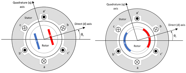
The motor magnetic field due to the permanent magnets creates a sinusoidal rate of change of flux with the motor angle.
For the axes convention, the phase-a aligns with d-axis when the motor angle θr is zero.
Three-Phase Sinusoidal Model Electrical System
The block implements these equations expressed in the motor flux reference frame (dq frame). All quantities in the motor reference frame are referred to as the stator.
The Lq and Ld inductances represent the relation between the phase inductance and the motor position due to the saliency of the motor magnets. For a surface mount PMSM, .
The equations use these variables.
Lq, Ld | q- and d-axis inductances (H) |
R | Resistance of the stator windings (ohm) |
iq, id | q- and d-axis currents (A) |
vq, vd | q- and d-axis voltages (V) |
ωm | Angular mechanical velocity of the motor (rad/s) |
ωe | Angular electrical velocity of the motor (rad/s) |
λpm | Permanent magnet flux linkage (Wb) |
| Ke | Back electromotive force (EMF) (Vpk_LL/krpm, where Vpk_LL is the peak voltage line-to-line measurement) |
Kt | Torque constant (N·m/A) Kt = Rated torque of motor / Ia_peak_rated, where Ia_peak_rated is the peak amplitude of phase-a at rated current operation. |
P | Number of pole pairs |
Te | Electromagnetic torque (Nm) |
Θe | Electrical angle (rad) |
Mechanical System
The motor angular velocity is given by:
The equations use these variables.
J | Combined inertia of motor and load (kgm^2) |
F | Combined viscous friction of motor and load (N·m/(rad/s)) |
θm | Motor mechanical angular position (rad) |
Tm | Motor shaft torque (Nm) |
Te | Electromagnetic torque (Nm) |
Tf | Motor shaft static friction torque (Nm) |
ωm | Angular mechanical velocity of the motor (rad/s) |
Power Accounting
For motor power accounting, the block implements these equations.
| Bus Signal | Description | Variable | Equations | ||
|---|---|---|---|---|---|
|
|
| Mechanical power | Pmot | |
PwrBus | Electrical power | Pbus | |||
|
| PwrElecLoss | Resistive power loss | Pelec | ||
PwrMechLoss | Mechanical power loss | Pmech | When Port Configuration is set to
When Port Configuration is
set to | ||
|
| PwrMtrStored | Stored motor power | Pstr | ||
The equations use these variables.
Rs | Stator resistance (ohm) |
ia, ib, ic | Stator phase a, b, and c current (A) |
isq, isd | Stator q- and d-axis currents (A) |
van, vbn, vcn | Stator phase a, b, and c voltage (V) |
ωm | Angular mechanical velocity of the motor (rad/s) |
F | Combined motor and load viscous damping N·m/(rad/s) |
Te | Electromagnetic torque (Nm) |
Tf | Combined motor and load friction torque (Nm) |
Amplitude Invariant dq Transformation
The block uses these equations to implement amplitude invariant dq transformation to ensure that the dq and three phase amplitudes are equal.
The equations use these variables.
Θda | dq stator electrical angle with respect to the rotor a-axis (rad) |
vsq, vsd | Stator q- and d-axis voltages (V) |
isq, isd | Stator q- and d-axis currents (A) |
| va, vb, vc | Stator voltage phases a, b, c (V) |
| ia, ib, ic | Stator currents phases a, b, c (A) |
Examples

Field-Oriented Control (FOC) of PMSM Using Hardware-in-the-Loop (HIL) Simulation
Uses hardware-in-the-loop (HIL) simulation to implement the field-oriented control (FOC) algorithm to control the speed of a three-phase permanent magnet synchronous motor (PMSM). The FOC algorithm requires rotor position feedback, which is obtained by a quadrature encoder sensor. For more information on FOC, see Field-Oriented Control.
Ports
Input
Output
Parameters
Extended Capabilities
Version History
Introduced in R2022b