Simulate Phase-Shift Isolated Converter Control
R2026bThis example shows how to simulate closed-loop voltage regulation of isolated DC-DC converters using phase-shift control. You configure and simulate a shared Simscape™ Electrical™ full-bridge power stage for two topologies: Dual Active Bridge (DAB) and Phase-Shifted Full Bridge (PSFB).
In this example, you:
Review converter and controller parameters, then open the phase-shift bridge model
Examine the DAB and PSFB plant models and understand their component-level topology differences
Simulate DAB closed-loop voltage regulation and examine the series inductor current at steady state
Simulate PSFB closed-loop voltage regulation at its design operating point
Open the Model and Review Parameters
To review the converter and controller parameters before simulating, open phaseShiftBridgeControlParams. The script documents the plant component values, switching frequency, and transformer turns ratio. It also defines the topology-specific PI gains. The DAB gains (, ) are derived from a first-order plant model with a target crossover frequency of and a phase margin of 75°. The PSFB gains (, ) are derived from a second-order plant model (the output inductor Lo adds a pole) with a target crossover of and a phase margin of 90°. These are initial estimates suitable as a starting point. See the Conclusion section for tuning options. The model loads all parameters directly from the script when you open it.
open_system("phaseShiftBridgeControl")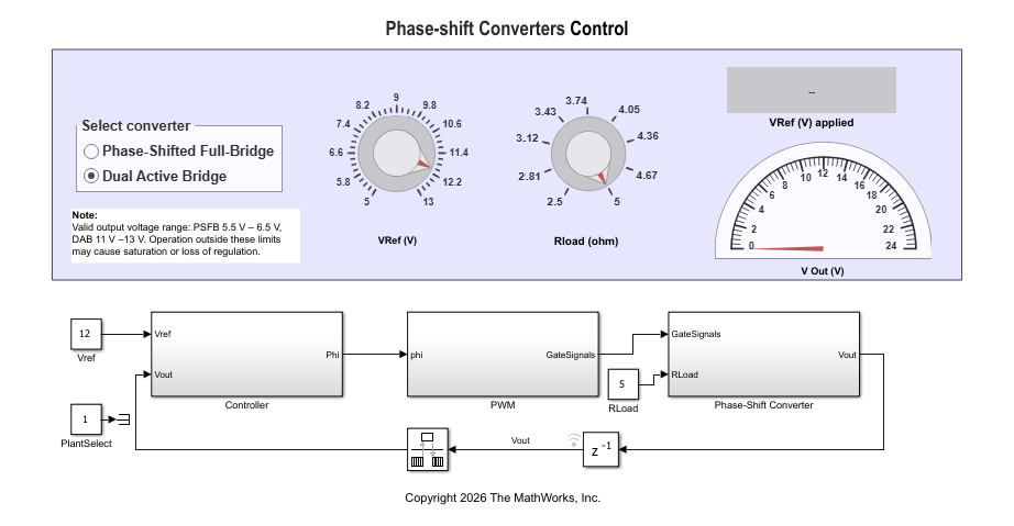
The model uses Variant Subsystems to switch between the DAB and PSFB topologies without modifying the circuit. The PlantSelect Constant block controls which plant and which controller variant is active. PlantSelect = 1 activates DAB, and PlantSelect = 0 activates PSFB. The dashboard Radio Button labeled "Select converter" lets you switch topologies interactively and writes directly to PlantSelect.
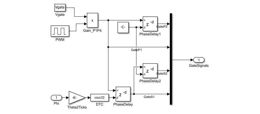
The phase-shift controller regulates output voltage by adjusting a phase angle between complementary switching signals. A discrete PI controller computes from the error between the voltage reference and the measured output voltage VoutFb, sampled at the switching period . Each topology has its own PI gains and phase-angle limits tuned to its plant dynamics. The dashboard also includes a Rload (ohm) knob to adjust the load resistance interactively.
Dual Active Bridge Plant Model
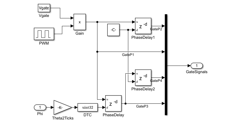
To examine the DAB circuit, open the Dual Active Bridge variant subsystem inside the Phase-Shift Converter subsystem. The DAB plant consists of a primary full H-bridge (switches P1–P4), an external series inductor L_series () in series with the transformer leakage, a center-tapped isolation transformer Xfmr (turns ratio ), a secondary full H-bridge (switches S1–S4), and an output filter capacitor Co ().
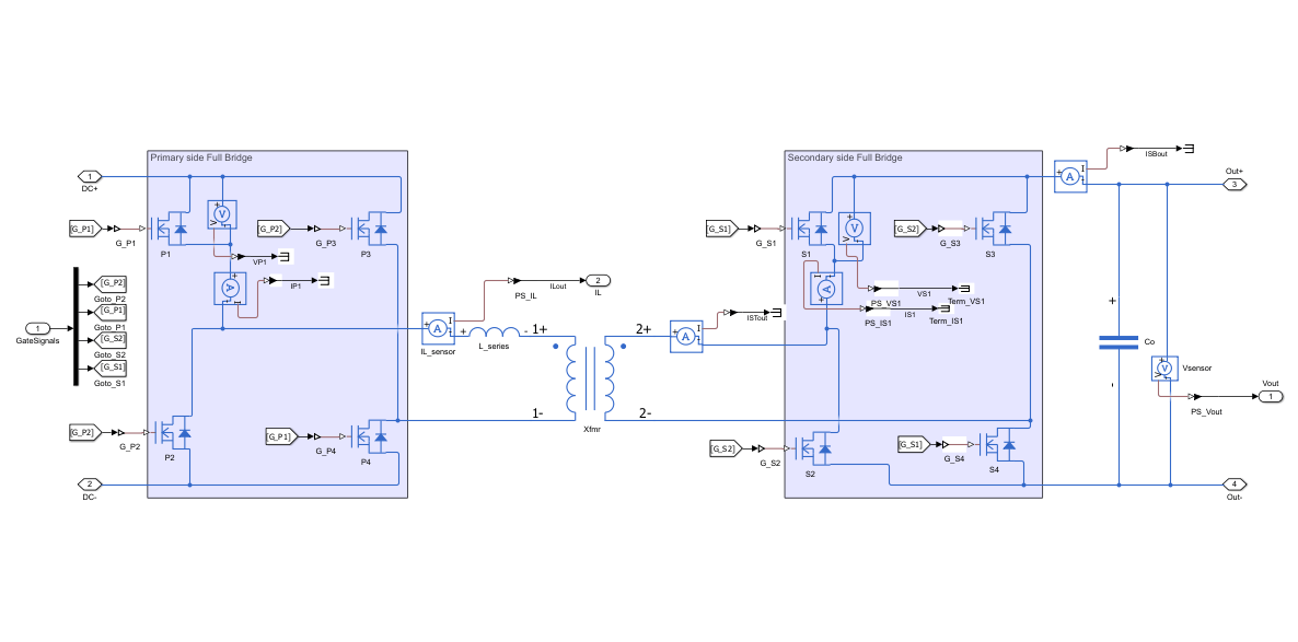
Power transfer in the DAB is bidirectional. The primary bridge generates a square-wave voltage and the secondary bridge generates , both at the switching frequency . The phase angle between and determines the volt-seconds applied to the total series inductance . This sets the average power transferred per cycle. A current sensor IL_sensor measures the series inductor current IL, and a voltage sensor Vsensor measures the output voltage VoutFb. Positive transfers power from primary to secondary. Negative reverses the flow and enables bidirectional operation.
Phase-Shifted Full Bridge Plant Model
To examine the PSFB circuit, open the Phase Shifted Full Bridge variant subsystem inside the Phase-Shift Converter subsystem. The PSFB plant shares the same primary H-bridge (P1–P4) and isolation transformer as the DAB, but replaces the active secondary bridge with a passive diode bridge (D1–D4) and adds an output filter inductor Lo () between the secondary rectifier and the output capacitor Co.
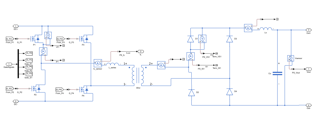
In the PSFB, the phase shift is applied between the leading leg (P1, P4) and the lagging leg (P2, P3) of the primary bridge. This phase difference controls the effective duty cycle of the transformer primary voltage. In turn, that sets the average volt-seconds applied to the output filter. Because the secondary is a passive diode bridge, the PSFB is unidirectional. Power flows only from primary to secondary. The output inductor Lo stores energy during the active interval and sustains current during the freewheeling interval. This freewheeling interval does not exist in the DAB. These topology differences result in a different plant transfer function and a different achievable output voltage at the same input voltage and turns ratio.
Simulate DAB Voltage Regulation
To simulate DAB operation, set PlantSelect to 1 and set the output voltage reference to 12 V, which is within the valid DAB regulation range of 11–13 V. The PI controller initializes at and ramps up the phase shift to regulate the output to 12 V within the 20 ms simulation window. The DAB PI gains (, ) are tuned for a crossover frequency of 333 Hz and a phase margin of 75°.
set_param("phaseShiftBridgeControl/PlantSelect", Value="1")
set_param("phaseShiftBridgeControl/Vref", Value="12")
simOut = sim("phaseShiftBridgeControl");
phaseShiftBridgeControlParams loaded
To retrieve the DAB output voltage waveform, query the Simulation Data Inspector (SDI) for the most recent run.
runIDs = Simulink.sdi.getAllRunIDs();
runDAB = Simulink.sdi.getRun(runIDs(end));
voutFbDABID = runDAB.getSignalIDsByName("VoutFb");
voutFbDAB = runDAB.getSignal(voutFbDABID(1)).Values;
To visualize the DAB voltage regulation transient, plot VoutFb against time with the 12 V reference marked.
figure
plot(voutFbDAB.Time * 1e3, voutFbDAB.Data, LineWidth=1.5)
yline(12, "--", "Vref = 12 V", LabelHorizontalAlignment="left")
xlabel("Time (ms)")
ylabel("Output Voltage (V)")
title("DAB Output Voltage Response")
grid on
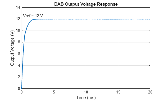
The DAB output voltage rises from 0 V and settles near 12 V. The crossover frequency of 333 Hz provides a well-damped response over the 20 ms window. The small steady-state error reflects the integrator still converging. Extend Tsim in phaseShiftBridgeControlParams to observe full steady-state settling.
Examine DAB Series Inductor Current
To understand how transfers energy in the DAB, examine the series inductor current IL at steady state. Use a 0.05 ms window near the end of the simulation to resolve individual switching cycles at 100 kHz. Each cycle is 10 µs wide.
tWindow = [19.95e-3, 20e-3];

ilDABID = runDAB.getSignalIDsByName("IL");
ilDAB = runDAB.getSignal(ilDABID(1)).Values;

figure
plot(ilDAB.Time * 1e3, ilDAB.Data, LineWidth=1.5)
xlim(tWindow * 1e3)
xlabel("Time (ms)")
ylabel("Current (A)")
title("DAB Series Inductor Current I_L at Steady State")
grid on
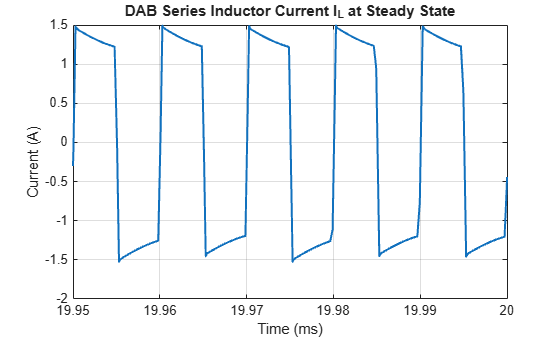
At steady state, the series inductor current IL is quasi-triangular and oscillates symmetrically around zero, confirming bidirectional energy transfer. Each half-cycle, the current ramps through as the phase angle drives a net volt-second imbalance across the inductance. The peak current magnitude at this operating point is set by and the inductance. A larger produces higher peak current and more energy transferred per cycle. The symmetric zero-crossing is a distinguishing characteristic of DAB operation. Unlike the PSFB, there is no freewheeling interval and no output inductor current, so the transformer current never sustains a DC offset.
Simulate PSFB Voltage Regulation
To simulate PSFB operation, set PlantSelect to 0 and set the output voltage reference to 6 V. This value is within the valid PSFB regulation range of 5.5 to 6.5 V. Setting Vref outside this range causes the PI controller to saturate and the output does not regulate correctly. The PSFB PI gains (, ) and phase-angle limit ( rad) are tuned for the PSFB plant transfer function. This plant differs from the DAB plant because of the output inductor and the passive secondary rectifier. The lower output voltage of the PSFB reflects the different voltage conversion ratio produced by the diode-bridge rectifier and duty-cycle modulation compared to the active secondary bridge.
set_param("phaseShiftBridgeControl/PlantSelect", Value="0")
set_param("phaseShiftBridgeControl/Vref", Value="6")
simOut = sim("phaseShiftBridgeControl");
phaseShiftBridgeControlParams loaded
To retrieve the PSFB output voltage, query the new SDI run created by the second simulation.
runIDs = Simulink.sdi.getAllRunIDs();
runPSFB = Simulink.sdi.getRun(runIDs(end));
voutFbPSFBID = runPSFB.getSignalIDsByName("VoutFb");
voutFbPSFB = runPSFB.getSignal(voutFbPSFBID(1)).Values;

figure
plot(voutFbPSFB.Time * 1e3, voutFbPSFB.Data, LineWidth=1.5)
yline(6, "--", "Vref = 6 V", LabelHorizontalAlignment="left")
xlabel("Time (ms)")
ylabel("Output Voltage (V)")
title("PSFB Output Voltage Response")
grid on
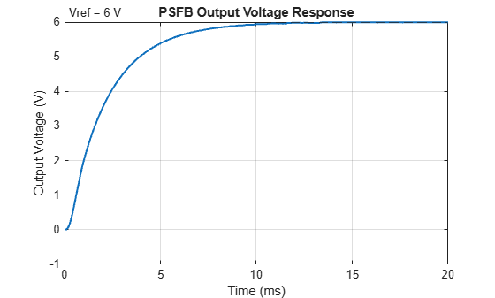
The PSFB output voltage rises from 0 V and settles near the 6 V reference. The PSFB modulates the effective duty cycle of the primary voltage waveform rather than shifting a secondary active bridge. The output inductor Lo stores energy during the active switching interval and sustains load current during the freewheeling interval. This gives the PSFB a second-order output filter characteristic. The result is a slower, more damped transient than the first-order DAB plant.
Conclusion
The DAB topology uses two active full bridges to shift phase between primary and secondary sides. This enables bidirectional power flow and makes DAB well-suited for applications such as battery storage systems, EV on-board chargers, and solid-state transformers where energy must flow in both directions. The PSFB topology uses a single active primary bridge with a passive diode bridge secondary. This makes PSFB a simpler and lower-cost choice for unidirectional high-power supplies such as telecom rectifiers and server power units.
The PI controller gains in this example are designed for a specific operating point using a linearized plant model. To improve transient response for your own converter specs, you can retune the gains using the PID Tuner app (Control System Toolbox™). This app automates gain selection from a measured or identified frequency response. To linearize the Simscape Electrical plant directly from the model and extract a frequency-domain model for tuning, use the linearization tools in Simulink Control Design™.
To explore other operating points in this model, adjust Rload, lSeries, or the PI gains in phaseShiftBridgeControlParams and rerun the simulations. Keep Vref within the valid regulation range for each topology: 11–13 V for DAB and 5.5–6.5 V for PSFB.

