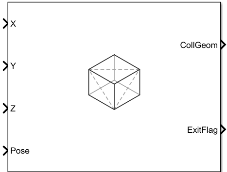
Collision Box
Libraries:
Robotics System Toolbox /
Collision Detection
Description
The Collision Box block outputs a box collision geometry that is axis-aligned with its body-fixed frame and has the origin of the body-fixed frame at the center of the box.
Examples
Open the Simulink® model. This model contains all five of the collision geometry blocks in the Collision Detection library and checks for collision between any two of the collision geometries. Note that the Collision Mesh block uses vertices from the exampleMeshVertices MAT file. The model loads the exampleMeshVertices MAT file when you open the model by using the PreLoadFcn callback.
model = "CollisionCheckingBetweenGeometries.slx";
open_system(model)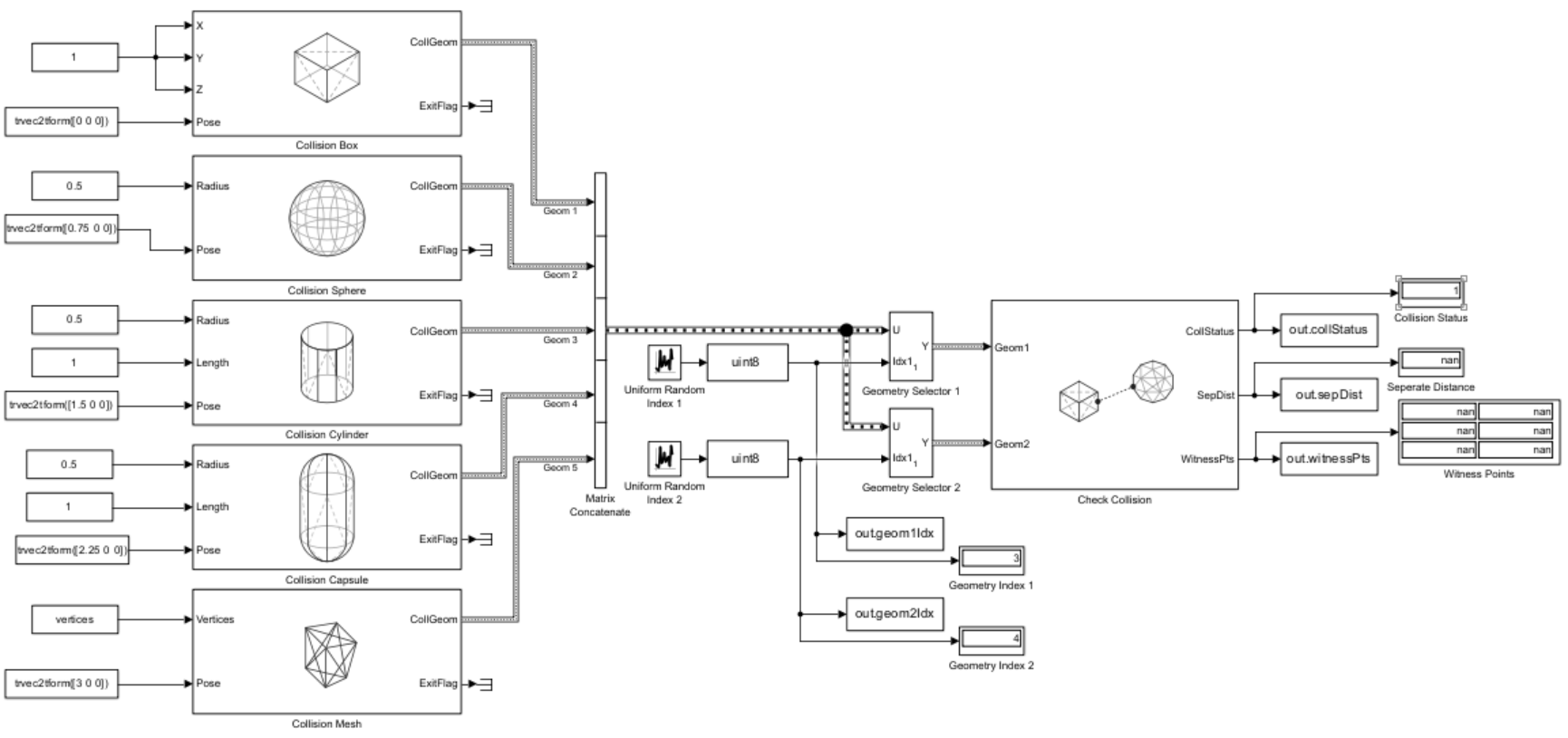
Simulate the model.
out = sim("CollisionCheckingBetweenGeometries.slx")### Building simulation target for model: 'CollisionCheckingBetweenGeometries'.
/mathworks/devel/bat/filer/batfs2566-0/Bdoc26a.3233028/build/runnable/matlab/bin/mex -R2018a -c -DMATLAB_MEX_FILE -I"/mathworks/devel/bat/filer/batfs2566-0/Bdoc26a.3233028/build/runnable/matlab/extern/include" -I"/mathworks/devel/bat/filer/batfs2566-0/Bdoc26a.3233028/build/runnable/matlab/simulink/include" -I"/mathworks/devel/bat/filer/batfs2566-0/Bdoc26a.3233028/build/runnable/matlab/rtw/c/src" -I"/tmp/Bdoc26a_3233028_1679788/tpe812315a/robotics-ex29391870" -I"/tmp/Bdoc26a_3233028_1679788/tpe812315a/robotics-ex29391870/slprj/_cprj" -I"/tmp/Bdoc26a_3233028_1679788/tpe812315a/robotics-ex29391870/slprj/_cgxe/CollisionCheckingBetweenGeometries/src" -I"/mathworks/devel/bat/filer/batfs2566-0/Bdoc26a.3233028/build/runnable/matlab/extern/include/shared_robotics" -I"/mathworks/devel/bat/filer/batfs2566-0/Bdoc26a.3233028/build/runnable/matlab/extern/include/shared_robotics/collfcncodegen" -I"/mathworks/devel/bat/filer/batfs2566-0/Bdoc26a.3233028/build/runnable/matlab/toolbox/shared/robotics/externalDependency/libccd/src" -I"/mathworks/devel/bat/filer/batfs2566-0/Bdoc26a.3233028/build/runnable/matlab/toolbox/shared/robotics/externalDependency/libccd/src/ccd" CFLAGS="\$CFLAGS -w -Dccd_EXPORTS" CollisionCheckingBetweenGeometries_cgxe.c
Building with 'gcc'.
MEX completed successfully.
/mathworks/devel/bat/filer/batfs2566-0/Bdoc26a.3233028/build/runnable/matlab/bin/mex -R2018a -c -DMATLAB_MEX_FILE -I"/mathworks/devel/bat/filer/batfs2566-0/Bdoc26a.3233028/build/runnable/matlab/extern/include" -I"/mathworks/devel/bat/filer/batfs2566-0/Bdoc26a.3233028/build/runnable/matlab/simulink/include" -I"/mathworks/devel/bat/filer/batfs2566-0/Bdoc26a.3233028/build/runnable/matlab/rtw/c/src" -I"/tmp/Bdoc26a_3233028_1679788/tpe812315a/robotics-ex29391870" -I"/tmp/Bdoc26a_3233028_1679788/tpe812315a/robotics-ex29391870/slprj/_cprj" -I"/tmp/Bdoc26a_3233028_1679788/tpe812315a/robotics-ex29391870/slprj/_cgxe/CollisionCheckingBetweenGeometries/src" -I"/mathworks/devel/bat/filer/batfs2566-0/Bdoc26a.3233028/build/runnable/matlab/extern/include/shared_robotics" -I"/mathworks/devel/bat/filer/batfs2566-0/Bdoc26a.3233028/build/runnable/matlab/extern/include/shared_robotics/collfcncodegen" -I"/mathworks/devel/bat/filer/batfs2566-0/Bdoc26a.3233028/build/runnable/matlab/toolbox/shared/robotics/externalDependency/libccd/src" -I"/mathworks/devel/bat/filer/batfs2566-0/Bdoc26a.3233028/build/runnable/matlab/toolbox/shared/robotics/externalDependency/libccd/src/ccd" CFLAGS="\$CFLAGS -w -Dccd_EXPORTS" CollisionCheckingBetweenGeometries_cgxe_registry.c
Building with 'gcc'.
MEX completed successfully.
/mathworks/devel/bat/filer/batfs2566-0/Bdoc26a.3233028/build/runnable/matlab/bin/mex -R2018a -c -DMATLAB_MEX_FILE -I"/mathworks/devel/bat/filer/batfs2566-0/Bdoc26a.3233028/build/runnable/matlab/extern/include" -I"/mathworks/devel/bat/filer/batfs2566-0/Bdoc26a.3233028/build/runnable/matlab/simulink/include" -I"/mathworks/devel/bat/filer/batfs2566-0/Bdoc26a.3233028/build/runnable/matlab/rtw/c/src" -I"/tmp/Bdoc26a_3233028_1679788/tpe812315a/robotics-ex29391870" -I"/tmp/Bdoc26a_3233028_1679788/tpe812315a/robotics-ex29391870/slprj/_cprj" -I"/tmp/Bdoc26a_3233028_1679788/tpe812315a/robotics-ex29391870/slprj/_cgxe/CollisionCheckingBetweenGeometries/src" -I"/mathworks/devel/bat/filer/batfs2566-0/Bdoc26a.3233028/build/runnable/matlab/extern/include/shared_robotics" -I"/mathworks/devel/bat/filer/batfs2566-0/Bdoc26a.3233028/build/runnable/matlab/extern/include/shared_robotics/collfcncodegen" -I"/mathworks/devel/bat/filer/batfs2566-0/Bdoc26a.3233028/build/runnable/matlab/toolbox/shared/robotics/externalDependency/libccd/src" -I"/mathworks/devel/bat/filer/batfs2566-0/Bdoc26a.3233028/build/runnable/matlab/toolbox/shared/robotics/externalDependency/libccd/src/ccd" CFLAGS="\$CFLAGS -w -Dccd_EXPORTS" m_GhFrblLuZIHYWtKepSDIND.c
Building with 'gcc'.
MEX completed successfully.
/mathworks/devel/bat/filer/batfs2566-0/Bdoc26a.3233028/build/runnable/matlab/bin/mex -R2018a -c -DMATLAB_MEX_FILE -I"/mathworks/devel/bat/filer/batfs2566-0/Bdoc26a.3233028/build/runnable/matlab/extern/include" -I"/mathworks/devel/bat/filer/batfs2566-0/Bdoc26a.3233028/build/runnable/matlab/simulink/include" -I"/mathworks/devel/bat/filer/batfs2566-0/Bdoc26a.3233028/build/runnable/matlab/rtw/c/src" -I"/tmp/Bdoc26a_3233028_1679788/tpe812315a/robotics-ex29391870" -I"/tmp/Bdoc26a_3233028_1679788/tpe812315a/robotics-ex29391870/slprj/_cprj" -I"/tmp/Bdoc26a_3233028_1679788/tpe812315a/robotics-ex29391870/slprj/_cgxe/CollisionCheckingBetweenGeometries/src" -I"/mathworks/devel/bat/filer/batfs2566-0/Bdoc26a.3233028/build/runnable/matlab/extern/include/shared_robotics" -I"/mathworks/devel/bat/filer/batfs2566-0/Bdoc26a.3233028/build/runnable/matlab/extern/include/shared_robotics/collfcncodegen" -I"/mathworks/devel/bat/filer/batfs2566-0/Bdoc26a.3233028/build/runnable/matlab/toolbox/shared/robotics/externalDependency/libccd/src" -I"/mathworks/devel/bat/filer/batfs2566-0/Bdoc26a.3233028/build/runnable/matlab/toolbox/shared/robotics/externalDependency/libccd/src/ccd" CFLAGS="\$CFLAGS -w -Dccd_EXPORTS" m_4heBl51EEsIlbER46Li5jD.c
Building with 'gcc'.
MEX completed successfully.
/mathworks/devel/bat/filer/batfs2566-0/Bdoc26a.3233028/build/runnable/matlab/bin/mex -R2018a -c -DMATLAB_MEX_FILE -I"/mathworks/devel/bat/filer/batfs2566-0/Bdoc26a.3233028/build/runnable/matlab/extern/include" -I"/mathworks/devel/bat/filer/batfs2566-0/Bdoc26a.3233028/build/runnable/matlab/simulink/include" -I"/mathworks/devel/bat/filer/batfs2566-0/Bdoc26a.3233028/build/runnable/matlab/rtw/c/src" -I"/tmp/Bdoc26a_3233028_1679788/tpe812315a/robotics-ex29391870" -I"/tmp/Bdoc26a_3233028_1679788/tpe812315a/robotics-ex29391870/slprj/_cprj" -I"/tmp/Bdoc26a_3233028_1679788/tpe812315a/robotics-ex29391870/slprj/_cgxe/CollisionCheckingBetweenGeometries/src" -I"/mathworks/devel/bat/filer/batfs2566-0/Bdoc26a.3233028/build/runnable/matlab/extern/include/shared_robotics" -I"/mathworks/devel/bat/filer/batfs2566-0/Bdoc26a.3233028/build/runnable/matlab/extern/include/shared_robotics/collfcncodegen" -I"/mathworks/devel/bat/filer/batfs2566-0/Bdoc26a.3233028/build/runnable/matlab/toolbox/shared/robotics/externalDependency/libccd/src" -I"/mathworks/devel/bat/filer/batfs2566-0/Bdoc26a.3233028/build/runnable/matlab/toolbox/shared/robotics/externalDependency/libccd/src/ccd" CFLAGS="\$CFLAGS -w -Dccd_EXPORTS" m_nO7LkfNziknjFjiV4wtacG.c
Building with 'gcc'.
MEX completed successfully.
/mathworks/devel/bat/filer/batfs2566-0/Bdoc26a.3233028/build/runnable/matlab/bin/mex -R2018a -c -DMATLAB_MEX_FILE -I"/mathworks/devel/bat/filer/batfs2566-0/Bdoc26a.3233028/build/runnable/matlab/extern/include" -I"/mathworks/devel/bat/filer/batfs2566-0/Bdoc26a.3233028/build/runnable/matlab/simulink/include" -I"/mathworks/devel/bat/filer/batfs2566-0/Bdoc26a.3233028/build/runnable/matlab/rtw/c/src" -I"/tmp/Bdoc26a_3233028_1679788/tpe812315a/robotics-ex29391870" -I"/tmp/Bdoc26a_3233028_1679788/tpe812315a/robotics-ex29391870/slprj/_cprj" -I"/tmp/Bdoc26a_3233028_1679788/tpe812315a/robotics-ex29391870/slprj/_cgxe/CollisionCheckingBetweenGeometries/src" -I"/mathworks/devel/bat/filer/batfs2566-0/Bdoc26a.3233028/build/runnable/matlab/extern/include/shared_robotics" -I"/mathworks/devel/bat/filer/batfs2566-0/Bdoc26a.3233028/build/runnable/matlab/extern/include/shared_robotics/collfcncodegen" -I"/mathworks/devel/bat/filer/batfs2566-0/Bdoc26a.3233028/build/runnable/matlab/toolbox/shared/robotics/externalDependency/libccd/src" -I"/mathworks/devel/bat/filer/batfs2566-0/Bdoc26a.3233028/build/runnable/matlab/toolbox/shared/robotics/externalDependency/libccd/src/ccd" CFLAGS="\$CFLAGS -w -Dccd_EXPORTS" m_pUaOgr0KJnPvwlP7Ju7YCG.c
Building with 'gcc'.
MEX completed successfully.
/mathworks/devel/bat/filer/batfs2566-0/Bdoc26a.3233028/build/runnable/matlab/bin/mex -R2018a -c -DMATLAB_MEX_FILE -I"/mathworks/devel/bat/filer/batfs2566-0/Bdoc26a.3233028/build/runnable/matlab/extern/include" -I"/mathworks/devel/bat/filer/batfs2566-0/Bdoc26a.3233028/build/runnable/matlab/simulink/include" -I"/mathworks/devel/bat/filer/batfs2566-0/Bdoc26a.3233028/build/runnable/matlab/rtw/c/src" -I"/tmp/Bdoc26a_3233028_1679788/tpe812315a/robotics-ex29391870" -I"/tmp/Bdoc26a_3233028_1679788/tpe812315a/robotics-ex29391870/slprj/_cprj" -I"/tmp/Bdoc26a_3233028_1679788/tpe812315a/robotics-ex29391870/slprj/_cgxe/CollisionCheckingBetweenGeometries/src" -I"/mathworks/devel/bat/filer/batfs2566-0/Bdoc26a.3233028/build/runnable/matlab/extern/include/shared_robotics" -I"/mathworks/devel/bat/filer/batfs2566-0/Bdoc26a.3233028/build/runnable/matlab/extern/include/shared_robotics/collfcncodegen" -I"/mathworks/devel/bat/filer/batfs2566-0/Bdoc26a.3233028/build/runnable/matlab/toolbox/shared/robotics/externalDependency/libccd/src" -I"/mathworks/devel/bat/filer/batfs2566-0/Bdoc26a.3233028/build/runnable/matlab/toolbox/shared/robotics/externalDependency/libccd/src/ccd" CFLAGS="\$CFLAGS -w -Dccd_EXPORTS" m_mqsM2RT6XtQ2LVLHaaUPnC.c
Building with 'gcc'.
MEX completed successfully.
/mathworks/devel/bat/filer/batfs2566-0/Bdoc26a.3233028/build/runnable/matlab/bin/mex -R2018a -c -DMATLAB_MEX_FILE -I"/mathworks/devel/bat/filer/batfs2566-0/Bdoc26a.3233028/build/runnable/matlab/extern/include" -I"/mathworks/devel/bat/filer/batfs2566-0/Bdoc26a.3233028/build/runnable/matlab/simulink/include" -I"/mathworks/devel/bat/filer/batfs2566-0/Bdoc26a.3233028/build/runnable/matlab/rtw/c/src" -I"/tmp/Bdoc26a_3233028_1679788/tpe812315a/robotics-ex29391870" -I"/tmp/Bdoc26a_3233028_1679788/tpe812315a/robotics-ex29391870/slprj/_cprj" -I"/tmp/Bdoc26a_3233028_1679788/tpe812315a/robotics-ex29391870/slprj/_cgxe/CollisionCheckingBetweenGeometries/src" -I"/mathworks/devel/bat/filer/batfs2566-0/Bdoc26a.3233028/build/runnable/matlab/extern/include/shared_robotics" -I"/mathworks/devel/bat/filer/batfs2566-0/Bdoc26a.3233028/build/runnable/matlab/extern/include/shared_robotics/collfcncodegen" -I"/mathworks/devel/bat/filer/batfs2566-0/Bdoc26a.3233028/build/runnable/matlab/toolbox/shared/robotics/externalDependency/libccd/src" -I"/mathworks/devel/bat/filer/batfs2566-0/Bdoc26a.3233028/build/runnable/matlab/toolbox/shared/robotics/externalDependency/libccd/src/ccd" CFLAGS="\$CFLAGS -w -Dccd_EXPORTS" m_sizVKYDMGZetO85ZcDubrF.c
Building with 'gcc'.
/tmp/Bdoc26a_3233028_1679788/tpe812315a/robotics-ex29391870/slprj/_cgxe/CollisionCheckingBetweenGeometries/src/m_sizVKYDMGZetO85ZcDubrF.c: In function ‘CollisionGeometryBuildableFunctional_intersect’:
/tmp/Bdoc26a_3233028_1679788/tpe812315a/robotics-ex29391870/slprj/_cgxe/CollisionCheckingBetweenGeometries/src/m_sizVKYDMGZetO85ZcDubrF.c:514:22: error: passing argument 16 of ‘fromMLToCollStruct’ from incompatible pointer type [-Wincompatible-pointer-types]
514 | &geom1struct.m_Vertices, &geom1struct.m_NumVertices,
| ^~~~~~~~~~~~~~~~~~~~~~~
| |
| const real64_T ** {aka const double **}
/tmp/Bdoc26a_3233028_1679788/tpe812315a/robotics-ex29391870/slprj/_cgxe/CollisionCheckingBetweenGeometries/src/m_sizVKYDMGZetO85ZcDubrF.c:114:43: note: expected ‘real64_T **’ {aka ‘double **’} but argument is of type ‘const real64_T **’ {aka ‘const double **’}
114 | real_T *geomstruct_m_Height, real64_T* *geomstruct_m_Vertices, uint32_T
| ~~~~~~~~~~~^~~~~~~~~~~~~~~~~~~~~
/tmp/Bdoc26a_3233028_1679788/tpe812315a/robotics-ex29391870/slprj/_cgxe/CollisionCheckingBetweenGeometries/src/m_sizVKYDMGZetO85ZcDubrF.c:521:22: error: passing argument 16 of ‘fromMLToCollStruct’ from incompatible pointer type [-Wincompatible-pointer-types]
521 | &geom2struct.m_Vertices, &geom2struct.m_NumVertices,
| ^~~~~~~~~~~~~~~~~~~~~~~
| |
| const real64_T ** {aka const double **}
/tmp/Bdoc26a_3233028_1679788/tpe812315a/robotics-ex29391870/slprj/_cgxe/CollisionCheckingBetweenGeometries/src/m_sizVKYDMGZetO85ZcDubrF.c:114:43: note: expected ‘real64_T **’ {aka ‘double **’} but argument is of type ‘const real64_T **’ {aka ‘const double **’}
114 | real_T *geomstruct_m_Height, real64_T* *geomstruct_m_Vertices, uint32_T
| ~~~~~~~~~~~^~~~~~~~~~~~~~~~~~~~~
gmake: *** [m_sizVKYDMGZetO85ZcDubrF.o] Error 255
### Build procedure for model: 'CollisionCheckingBetweenGeometries' aborted due to an error.
Get data from the simulation output.
collCheckingPairs = [out.geom1Idx.Data out.geom2Idx.Data];
collStatuses = out.collStatus.Data;
sepDistances = out.sepDist.Data;
witnessPoints = out.witnessPts.Data;
Ports
Input
Output
Parameters
More About
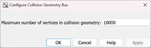
To configure the maximum number of vertices in a collision geometry block, click
Configure Collision Geometry Bus in the block mask to open the
Configure Collision Geometry Bus dialog box, and set the Maximum number of
vertices in collision geometry parameter. The default number of vertices is
10000.
Extended Capabilities
Version History
Introduced in R2025a