Getting Started with Simulink Coder Support Package for NXP FRDM-K64F Board
This example shows you how to use Simulink® Coder™ Support Package for NXP FRDM-K64F Board to run Simulink models on a FRDM-K64F board.
Introduction
Simulink Coder Support Package for NXP FRDM-K64F Board enables you to create and run Simulink models on a NXP FRDM-K64F board. The support package includes a library of Simulink blocks for configuring and accessing NXP FRDM-K64F peripherals and communication interfaces.
In this example, you learn how to configure a Simulink model to generate code for NXP FRDM-K64F board and run the generated code on the board. This model sets the color of the onboard RGB LED to red.
Prerequisites
If you are new to Simulink, complete the Interactive Simulink Tutorial.
If you are new to Simulink Coder, visit the Simulink Coder product page for an overview and tutorials.
To update your FRDM-K64F board with Segger J-Link firmware, follow the steps described in Install OpenSDAv2 Firmware on FRDM-K64F Board.
Required Hardware
To run this example, you need this hardware:
NXP FRDM-K64F board
USB type A to Micro-B cable
Open Model
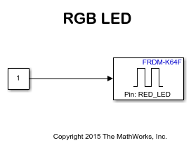
Open the example model freedomk64f_RGB_LED.
Task 1 - Connect an FRDM-K64F Board to Development Machine
Connect a FRDM-K64F board to a development machine.
1. Plug in a Micro USB cable from a USB port on the development machine to the OpenSDA micro-B USB connector on the FRDM-K64F board.
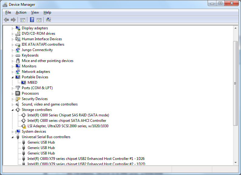
2. mbed CMSIS-DAP Firmware: If your FRDM-K64F board is loaded with mbed OpenSDA v2 firmware, then it appears as a removable storage drive with a volume label of MBED on Windows®.
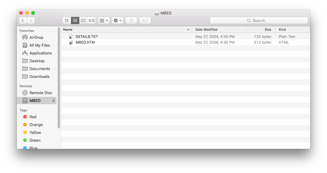
On Mac, the board appears as a removable storage drive with a volume label of MBED.
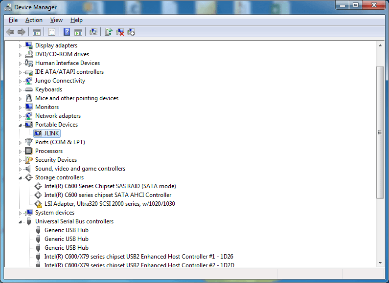
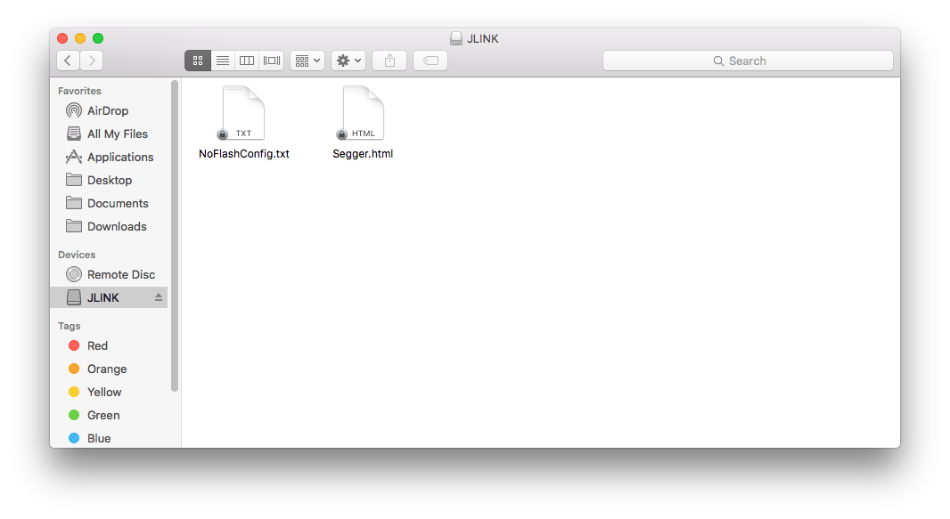
Segger J-Link Firmware: If your FRDM-K64F board is loaded with Segger J-Link OpenSDA v2 firmware, then the board appears as a removable storage drive with a volume label of JLINK on Windows.
On Mac, the board appears as a removable storage drive with a volume label of JLINK.
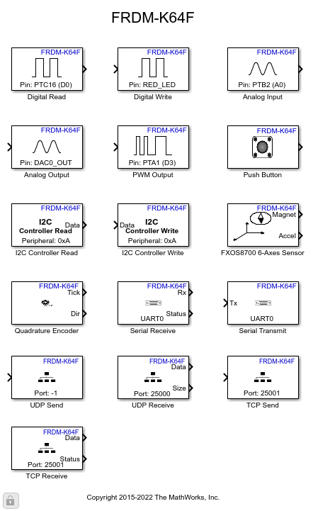
Task 2 - Review NXP FRDM-K64F Support Package Block Library
1. Open the Simulink Library Browser and navigate to Simulink Coder Support Package for NXP FRDM-K64F Board.
2. Double-click the Digital Write block. Review the block mask, which contains a description of the block and block inputs.
Open Model
Open the |frdmk64flib|block library.
Task 3 - Create and Run a Model on NXP FRDM-K64F Board
Create a Simulink model that sets the color of the RGB LED to red.
1. In MATLAB, select HOME > New > Simulink Model. This opens the Simulink Start Page. % 2. In the Simulink Start Page, expand Simulink and select the Blank Model Template. Click Create Model.
3. Drag the Constant block from the Simulink Sources library to your model. Set the value of Constant block to 1.
3. Drag the Digital Write block from the FRDM-K64F library to the model.
4. Double-click the Digital Write block and select RED_LED from the Pin menu.
5. Connect the Constant block to the input of Digital Write block.
6. Connect the NXP FRDM-K64F Board to your computer with a USB cable.
7. In your Simulink model, click Configuration Parameters.

8. When the Configuration Parameters dialog box opens up, navigate to the Hardware Implementation pane.
Set the Hardware board parameter to
NXP FRDM-K64F.On the Target Hardware Resources pane, Set the Build action to
Build, load and runto automatically download the generated binary file onto the connected NXP FRDM-K64F board.
9. Click OK.
10. In the model window toolstrip, click Build Model. The model is deployed to the NXP FRDM-K64F board.

The RGB LED is set to the color red.
11. Save your model.
Other Things to Try with Digital Write Block
For example:
Create and run a model that turns the RGB LED to different colors.
Create and run a model that toggles the RGB LED to R, G, and B colors.