CCSDS High Data Rate Optical Link Simulation for 1550nm
R2026bThis example shows how to measure the bit error rate (BER) in a Consultative Committee for Space Data Systems (CCSDS) optical communications high data rate (HDR) 1550 nm optical link with channel impairments. The simulation generates CCSDS-compliant waveforms, applies channel effects such as Doppler shift, laser phase noise, sampling clock offset, and additive white Gaussian (AWGN) noise, and recovers the transmitted data using a complete receiver chain. The simulation chain follows the coding and modulation schemes specified in the CCSDS 141.10-O-1 standard [1]. In this example, HDR optical communications aim to support various near-Earth optical communication link applications by using wavelengths in the 1550 nm range, where a high data rate is the primary consideration in the link design. These links operate at rates of approximately 100 Gbps, enabling large data transfers within short contact times.
CCSDS HDR 1550 nm Optical Link Overview
The CCSDS HDR 1550 nm optical communications standard defines a high-speed optical link for space-to-space, space-to-air, air-to-space, space-to-ground, and ground-to-space links using 1550 nm wavelength lasers. The standard supports multiple phase modulation schemes, including differential phase-shift keying (DPSK), differential quadrature phase-shift keying (DQPSK), binary phase-shift keying (BPSK), and quadrature phase-shift keying (QPSK). It also supports non-return-to-zero (NRZ), return-to-zero 33% (RZ33), and return-to-zero 50% (RZ50) intensity modulation formats, along with Reed-Solomon (RS) or Bose-Chaudhuri-Hocquenghem and low-density parity-check (BCH-LDPC) forward error correction (FEC) codes.
This figure shows the CCSDS HDR 1550 nm optical link architecture.

This example simulates the complete link-level chain from transmitter to receiver. The simulation sweeps over multiple energy per bit to noise power ratio (Eb/N0) values and computes the BER at each operating point.
This example models these channel impairments.
Carrier frequency offset due to Doppler shift
Laser phase noise using a Wiener process model
Sample clock offset due to transmitter and receiver timing mismatch
AWGN
Configuration and Simulation Parameters
Specify the configuration parameters for HDR 1550 nm waveform generation and data recovery. Set the synchronization marked frame (SMF) generation method, FEC code, phase modulation, intensity modulation, symbol rate, and burst parameter to evaluate their impact on the BER performance. This example supports only continuous frames so set BurstParameter to 0.
cfgParams.SMFGenerationMethod ="ASM"; % ASM | GFP cfgParams.NumBytesInFrame = 1504; cfgParams.FECCode =
"RS"; % RS | BCH-LDPC if strcmp(cfgParams.FECCode,"BCH-LDPC") cfgParams.LDPCCodeRate =
"1/4"; % 1/4 | 1/3 | 2/5 | 1/2 | 3/5 | 2/3 | 3/4 | 4/5 | 5/6 | 8/9 | 9/10 end cfgParams.PhaseModulation =
"QPSK"; % QPSK | BPSK | DPSK | DQPSK cfgParams.IntensityModulation =
"RZ50"; % RZ50 | NRZ | RZ33 cfgParams.SymbolRate =
10e9; % 10GHz | 2.5GHz cfgParams.SamplesPerSymbol = 6; cfgParams.BurstParameter = 0;
Specify the Eb/N0 sweep range and number of iterations for each operating point. Increasing numIterPerSNR produces a smoother BER curve but increases simulation time.
EbN0dB = 9:0.5:11;  % Eb/N0 sweep range in dB
numIterPerSNR = 12; % Number of iterations per Eb/N0 point
Define the fixed channel impairment parameters. These parameters model the Doppler-induced frequency offset, the combined linewidth of the transmitter and local oscillator lasers, and sample clock offset in parts per million (ppm).
channelParams.FreqOffset = 50e6;        % Carrier frequency offset (Hz)
channelParams.CombinedLinewidth = 50e3; % Combined Tx and LO laser linewidth (Hz) for calculating laser phase noise variance
channelParams.SamplingClockOffset = 5;  % Sample clock offset between Tx and Rx (ppm)
BER Processing Loop
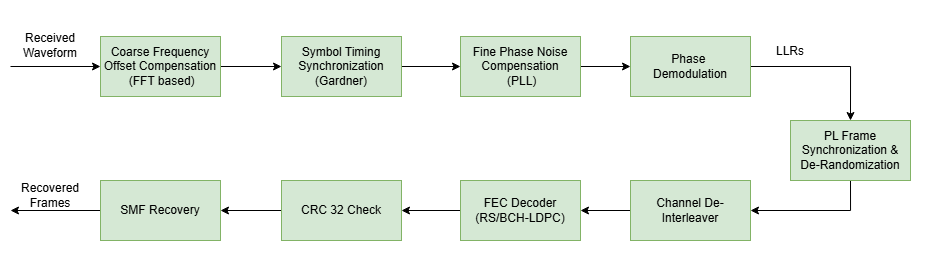
This figure shows the receiver processing chain for the CCSDS HDR 1550 nm optical link, including timing synchronization, frequency and phase compensation, demodulation, and bit recovery.
To analyze the BER performance for a CCSDS HDR 1550 nm optical link, the simulation performs these steps for each Eb/N0 point.
Generate the HDR 1550 nm waveform using
HelperCCSDSHDR1550WaveformGenerator. For more information about transmitter processing, see the CCSDS Optical High Data Rate Waveform Generation for 1550nm example.Apply carrier frequency offset using the
comm.PhaseFrequencyOffsetSystem object™. This models the Doppler shift experienced due to relative motion between the transmitter and receiver. The frequency offset accumulates phase linearly over time, rotating the signal constellation and requiring compensation at the receiver.Apply laser phase noise modeled as a continuous Wiener process with variance proportional to the combined laser linewidth. Generate phase increments from a zero-mean Gaussian distribution with variance , where is the combined linewidth of the transmitter and local oscillator lasers and is the sample period. The cumulative phase noise is continuous across iterations to model the nonstationary nature of laser phase drift.
Apply sample clock offset using the
comm.SampleRateOffsetSystem object. This models the timing mismatch between the transmitter and receiver sampling clocks, specified in ppm. The clock offset causes the received signal to be sampled at a slightly different rate than the transmit rate, resulting in inter-symbol interference and requiring timing recovery at the receiver.Add AWGN using the per-sample signal-to-noise ratio (SNR) derived from the current Eb/N0 value. The noise is scaled relative to the measured signal power to accurately model the receiver thermal and shot noise environment.
Perform symbol timing synchronization using the
comm.SymbolSynchronizerwith a Gardner timing error detector (TED). The Gardner TED is a non-data-aided algorithm that estimates timing errors by comparing midpoint samples with adjacent symbol samples. The synchronizer uses a configurable damping factor and normalized loop bandwidth to track and correct the sampling phase, and outputs one sample per symbol at the optimal sampling instant.Perform frequency and phase compensation The compensation scheme consists of a coarse compensation (CC) stage followed by a fine compensation (FC) stage. In the coarse stage, frequency offset compensation is applied using the
comm.CoarseFrequencyCompensatorSystem object, which estimates the frequency offset using a fast Fourier transform (FFT)-based M-th power algorithm. After coarse compensation, the fine compensation stage corrects the residual frequency error and laser phase noise using acomm.CarrierSynchronizerphase-locked loop (PLL).Demodulate the received symbols using
HelperCCSDSHDR1550Demodulatehelper function to obtain log-likelihood ratios (LLRs). For coherent modulation schemes BPSK and QPSK, the demodulator computes soft-decision LLRs based on the Euclidean distance from received symbols to constellation points. For differential modulation schemes DPSK and DQPSK, differential detection is performed by multiplying each symbol with the conjugate of the previous symbol before computing LLRs. The soft LLRs preserve reliability information for the subsequent FEC decoder.Recover the transmitted bits using
HelperCCSDSHDR1550BitRecovererhelper System object. This helper performs frame synchronization by correlating received soft LLRs against frame acquisition sequence (FAS) patterns and correcting phase ambiguities. It then de-randomizes the synchronized data using a pseudonoise (PN) sequence, applies channel de-interleaving through convolutional deinterleavers to reverse the transmitter-side interleaving, applies RS or BCH and LDPC FEC decoding, verifies data integrity using cyclic redundancy check (CRC-32) detection, and extracts the original data payload through SMF recovery using either attached sync marker (ASM) correlation synchronization or generic framing procedure (GFP) frame header parsing.Compute the BER by comparing the recovered frames with the transmitted data using embedded frame sequence numbers. Each transmitted frame embeds a 16-bit sequence number in its first two bytes, which allows the receiver to match recovered frames to their corresponding transmitted frames even when frame losses occur. The BER is computed as the ratio of total bit errors to total bits compared across all successfully recovered frames. Frames that are not recovered due to synchronization failure or uncorrectable FEC errors are counted as lost frames and reported separately.
% Compute derived parameters for modulation type, SNR calculation,
% frame sizing, and timing synchronization.
switch cfgParams.PhaseModulation
    case {"DPSK","BPSK"}
        bitsPerSymbol = 1;
        coarseModType = "BPSK";
    case {"DQPSK","QPSK"}
        bitsPerSymbol = 2;
        coarseModType = "QPSK";
end
if strcmp(cfgParams.FECCode,"BCH-LDPC")
    rateParts = split(cfgParams.LDPCCodeRate, "/");
    codeRate = str2double(rateParts(1))/str2double(rateParts(2));
else                                                              % RS encoding
    codeRate = 209/225;
end
sampleRate = cfgParams.SamplesPerSymbol*cfgParams.SymbolRate;

sps = cfgParams.SamplesPerSymbol;
plFrameLen = 65824;                               % PLFM(1024) + FEC codeword(64800)
samplesPerFrame = (plFrameLen/bitsPerSymbol)*sps;
numFramesPerIter = 5;                             % Number of physical layer frames generated per iteration
normalizedLoopBandwidth = 0.15;
dampingFactor = 1.0;

% Channel impairment objects
fqyoffsetobj = comm.PhaseFrequencyOffset( ...
    FrequencyOffset=channelParams.FreqOffset, ...
    PhaseOffset=0, ...
    SampleRate=sampleRate);
samplerateoffsetobj = comm.SampleRateOffset(Offset=channelParams.SamplingClockOffset);
phaseNoiseVar = 2*pi*channelParams.CombinedLinewidth/sampleRate;

% Extract configuration fields into scalar variables to avoid
% broadcasting the entire cfgParams struct to parfor workers.
smfMethod = cfgParams.SMFGenerationMethod;
numBytesInFrame = cfgParams.NumBytesInFrame;
fecCode = cfgParams.FECCode;
phaseMod = cfgParams.PhaseModulation;
intensityMod = cfgParams.IntensityModulation;
symbolRate = cfgParams.SymbolRate;
sampPerSym = cfgParams.SamplesPerSymbol;
burstParam = cfgParams.BurstParameter;
if strcmp(fecCode,"BCH-LDPC")
    ldpcRate = cfgParams.LDPCCodeRate;
end

% Receiver objects
timingRecObj = comm.SymbolSynchronizer( ...
    TimingErrorDetector="Gardner (non-data-aided)", ...
    SamplesPerSymbol=sps, ...
    DampingFactor=dampingFactor, ...
    NormalizedLoopBandwidth=normalizedLoopBandwidth);
coarseFreqCompObj = comm.CoarseFrequencyCompensator( ...
    Modulation=coarseModType, ...
    SampleRate=sampleRate, ...
    FrequencyResolution=1e6);
carrierSyncObj = comm.CarrierSynchronizer( ...
    Modulation=coarseModType, ...
    SamplesPerSymbol=1, ...
    DampingFactor=1.0, ...
    NormalizedLoopBandwidth=0.01);
bitRecoverObj = HelperCCSDSHDR1550BitRecoverer( ...
    SMFGenerationMethod=smfMethod, ...
    FECCode=fecCode, ...
    PhaseModulation=phaseMod);
if strcmp(smfMethod,"ASM")
    bitRecoverObj.NumBytesInFrame = numBytesInFrame;
end
if strcmp(fecCode,"BCH-LDPC")
    bitRecoverObj.LDPCCodeRate = ldpcRate;
end

% Initialize variables to compute BER
numSNR = length(EbN0dB);
ber = zeros(numSNR,1);
framesLostPerSNR = zeros(numSNR,1);
totalFrames = numIterPerSNR*numFramesPerIter;

fprintf("\n--- CCSDS HDR 1550 nm BER Simulation Started ---\n");
--- CCSDS HDR 1550 nm BER Simulation Started ---
fprintf("Phase Modulation: %s\n",cfgParams.PhaseModulation);Phase Modulation: QPSK
fprintf("Intensity Modulation: %s\n",cfgParams.IntensityModulation);Intensity Modulation: RZ50
fprintf("FEC Code: %s\n",cfgParams.FECCode);FEC Code: RS
fprintf("Frequency Offset: %.1f MHz\n",channelParams.FreqOffset/1e6);Frequency Offset: 50.0 MHz
fprintf("Sampling Clock Offset: %.1f ppm\n",channelParams.SamplingClockOffset);Sampling Clock Offset: 5.0 ppm
fprintf("Eb/N0 Range: %.1f to %.1f dB\n",EbN0dB(1),EbN0dB(end));Eb/N0 Range: 9.0 to 11.0 dB
fprintf("Number of iterations per Eb/N0 point: %d\n\n",numIterPerSNR);Number of iterations per Eb/N0 point: 12
for isnr = 1:numSNR % Comment out for parallel computing
% parfor isnr = 1:numSNR % Uncomment for parallel computing
    % To reduce the total simulation time, you can execute this loop in
    % parallel by using Parallel Computing Toolbox features. Comment
    % out the for-loop statement and uncomment the parfor-loop statement.
    % If Parallel Computing Toolbox is not installed, parfor-loop defaults
    % to a for-loop statement. Because the parfor-loop iterations are
    % executed in parallel in a nondeterministic order, the simulation
    % information displayed for each transmit power point can be intertwined.


    % Reset the random number generator so that each SNR iteration
    % experiences the same realization
    rng("default");

    % The HelperCCSDSHDR1550WaveformGenerator is created inside the loop
    % because its IsEndOfTransmission property is modified during iteration.
    % The remaining System objects are created outside and reset at the
    % start of each iteration.
    waveGen = HelperCCSDSHDR1550WaveformGenerator( ...
        SMFGenerationMethod=smfMethod, ...
        NumBytesInFrame=numBytesInFrame, ...
        FECCode=fecCode, ...
        PhaseModulation=phaseMod, ...
        IntensityModulation=intensityMod, ...
        SymbolRate=symbolRate, ...
        SamplesPerSymbol=sampPerSym, ...
        BurstParameter=burstParam, ...
        IsEndOfTransmission=false);
    if strcmp(fecCode,"BCH-LDPC")
        waveGen.LDPCCodeRate = ldpcRate;
    end

    % Reset stateful objects for this Eb/N0 point
    reset(fqyoffsetobj);
    reset(samplerateoffsetobj);
    reset(timingRecObj);
    reset(coarseFreqCompObj);
    reset(carrierSyncObj);
    reset(bitRecoverObj);

    % Compute per-sample SNR for this Eb/N0 point
    SNRdB = EbN0dB(isnr) + 10*log10(bitsPerSymbol*codeRate/sampPerSym);

    errorRateObj = comm.ErrorRate;
    berStats = zeros(3,1);                            % [ErrorRate; NumErrors; NumComparisons]
    allTxData = zeros(numBytesInFrame*8,totalFrames);
    numRecoveredFrames = 0;
    phaseNoiseState = 0;
    nextCoarseSym = [];
    prevDemodSym = 1;

    for iter = 1:numIterPerSNR

        %% Transmitter
        % The first 16 bits in each frame are encoded with a frame sequence
        % number to identify lost frames and calculate BER. This mechanism
        % is not specified in the CCSDS coding and synchronization layer
        % standard but is similar to data link layer frame numbering, which
        % is out of scope of this example.
        data = randi([0 1],numBytesInFrame*8,numFramesPerIter);
        globalFrameIdx = (iter-1)*numFramesPerIter + (1:numFramesPerIter);
        data(1:16,:) = int2bit(globalFrameIdx,16);
        allTxData(:,globalFrameIdx) = data;
        if iter == numIterPerSNR
            waveGen.IsEndOfTransmission = true;
        end
        hdrWaveform = waveGen(data(:));
        numSamples = length(hdrWaveform);

        %% Channel impairments
        % Frequency offset due to doppler shift
        rxWaveform = fqyoffsetobj(hdrWaveform);

        % Laser phase noise using continuous Wiener process
        phaseIncrements = sqrt(phaseNoiseVar)*randn(numSamples,1);
        laserPhaseNoise = phaseNoiseState + cumsum(phaseIncrements);
        phaseNoiseState = laserPhaseNoise(end);
        rxWaveform = rxWaveform.*exp(1j*laserPhaseNoise);

        % Sampling rate offset due to clock mismatch
        rxWaveform = samplerateoffsetobj(rxWaveform);

        % AWGN
        sigPower_dBW = 10*log10(mean(abs(hdrWaveform).^2));
        rxWaveform = awgn(rxWaveform,SNRdB,sigPower_dBW);

        %% Receiver
        % Coarse frequency compensation and symbol synchronization
        if iter == numIterPerSNR
            rxFrames = buffer([nextCoarseSym; rxWaveform],samplesPerFrame);
            nextCoarseSym = [];
        else
            [rxFrames,nextCoarseSym] = buffer([nextCoarseSym; rxWaveform],samplesPerFrame);
        end
        numChunks = size(rxFrames,2);
        timingOut = cell(numChunks,1);
        for chunkIdx = 1:numChunks
            coarseCompensated = coarseFreqCompObj(rxFrames(:,chunkIdx));
            timingOut{chunkIdx} = timingRecObj(coarseCompensated);
        end
        rxSymbols = vertcat(timingOut{:});

        % Fine frequency and phase compensation
        if isempty(rxSymbols)
            continue;
        end
        rxSymbols = carrierSyncObj(rxSymbols);

        % Demodulation
        if ismember(phaseMod,["DPSK","DQPSK"])
            demodIn = [prevDemodSym; rxSymbols];
            prevDemodSym = rxSymbols(end);
        else
            demodIn = rxSymbols;
        end
        rxLLR = HelperCCSDSHDR1550Demodulate(demodIn,phaseMod);

        % Bit recovery
        if ~isempty(rxLLR)
            recoveredFrames = bitRecoverObj(rxLLR);
        else
            recoveredFrames = [];
        end

        % BER accumulation using comm.ErrorRate
        if ~isempty(recoveredFrames)
            if iscell(recoveredFrames)
                for fIdx = 1:numel(recoveredFrames)
                    frame = recoveredFrames{fIdx};
                    if length(frame) < 16
                        continue;
                    end
                    seqNum = bit2int(frame(1:16),16);
                    if seqNum >= 1 && seqNum <= totalFrames
                        numBitsToCompare = min(length(frame),size(allTxData,1));
                        berStats = errorRateObj(allTxData(1:numBitsToCompare,seqNum), ...
                            frame(1:numBitsToCompare));
                        numRecoveredFrames = numRecoveredFrames + 1;
                    end
                end
            else
                seqNums = bit2int(recoveredFrames(1:16,:),16).';
                validMask = seqNums >= 1 & seqNums <= totalFrames;
                validSeqNums = seqNums(validMask);
                validFrames = recoveredFrames(:,validMask);
                txBits = allTxData(:,validSeqNums);
                berStats = errorRateObj(txBits(:),validFrames(:));
                numRecoveredFrames = numRecoveredFrames + numel(validSeqNums);
            end
        end

    end

    % Record BER for this Eb/N0 point
    numFramesLost = totalFrames - numRecoveredFrames;
    if berStats(3) > 0
        ber(isnr) = berStats(1);
    else
        ber(isnr) = NaN;
    end
    framesLostPerSNR(isnr) = numFramesLost;

    fprintf("Completed Eb/N0 = %.1f dB (%d/%d) | BER: %e | Frames lost: %d/%d\n", ...
        EbN0dB(isnr),isnr,numSNR,ber(isnr),numFramesLost,totalFrames);
end
Completed Eb/N0 = 9.0 dB (1/5) | BER: 1.512752e-01 | Frames lost: 46/60
Completed Eb/N0 = 9.5 dB (2/5) | BER: 5.293622e-02 | Frames lost: 32/60
Completed Eb/N0 = 10.0 dB (3/5) | BER: 1.094304e-03 | Frames lost: 0/60
Completed Eb/N0 = 10.5 dB (4/5) | BER: 4.155585e-05 | Frames lost: 0/60
Completed Eb/N0 = 11.0 dB (5/5) | BER: 1.246676e-05 | Frames lost: 0/60
Plot BER
Plot the BER curve as a function of Eb/N0. The BER decreases with increasing Eb/N0, exhibiting the waterfall characteristic typical of coded optical links. A NaN value indicates that no frames were successfully recovered at that operating point, which occurs when the SNR is too low for the receiver to achieve frame synchronization.
figure;
semilogy(EbN0dB,ber,"-o","LineWidth",1.5);
grid on;
xlabel("E_b/N_0 (dB)");
ylabel("BER");
title("CCSDS HDR 1550 nm - BER vs E_b/N_0");
legend(sprintf("%s, %s, %s",cfgParams.PhaseModulation, ...
    cfgParams.IntensityModulation,cfgParams.FECCode),"Location","southwest");
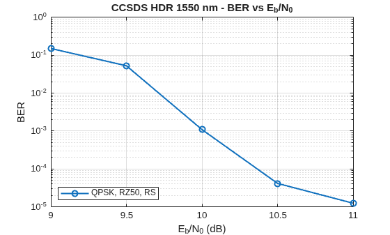
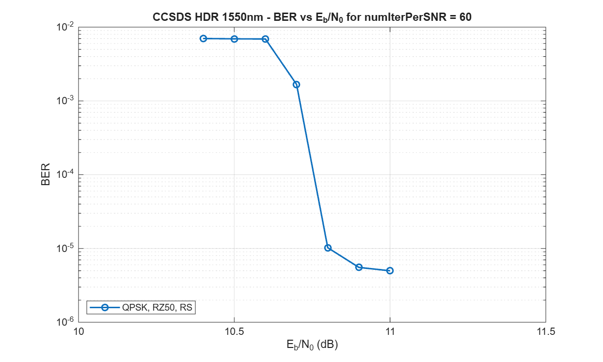
This figure shows the BER performance curve for QPSK phase modulation, RZ50 intensity modulation, and RS FEC for numIterPerSNR = 60.
Further Exploration
You can explore these variations of the simulation:
Change the phase modulation scheme to DPSK or DQPSK and observe the BER performance difference with differential versus coherent detection.
Change the intensity modulation format between NRZ, RZ33, and RZ50 to study pulse shaping effects.
Switch the FEC code from RS to BCH-LDPC and vary the LDPC code rate to compare coding gains.
Adjust the channel impairment parameters such as frequency offset, linewidth, clock offset to evaluate receiver robustness.
Increase
numIterPerSNRto obtain smoother BER curves at low error rates.Enable parallel computing by uncommenting the
parforstatement and commenting theforstatement in the processing loop to reduce simulation time using the Parallel Computing Toolbox.
Supporting Files
The example uses these helper files.
HelperCCSDSHDR1550WaveformGenerator.m— Generate the HDR 1550 nm optical waveformHelperCCSDSHDR1550BitRecoverer.m— Perform frame synchronization, de-interleaving, FEC decoding, CRC verification, and SMF recoveryHelperCCSDSHDR1550Demodulate.m— Demodulate received symbols to obtain LLRsHelperCCSDSHDRIntensityModulation.m— Apply intensity modulation (NRZ, RZ33, RZ50)HelperCCSDSHDRBCHEncode.m— Perform BCH encoding for BCH-LDPC FEC
References
[1] The Consultative Committee for Space Data Systems. Optical High Data Rate (HDR) Communication -1550 nm, Experimental Specification, Issue 1. CCSDS 141.10-O-1. Washington, D.C.: CCSDS, 2022.
[2] Generic Framing Procedure. ITU-T G.7041/Y.1303. Geneva: ITU, 2016.
[3] ETSI Standard EN 302 307-1 V1.4.1(2014-11). Digital Video Broadcasting (DVB); Second Generation Framing Structure, Channel Coding and Modulation Systems for Broadcasting, Interactive Services, News Gathering and other Broadband Satellite Applications (DVB-S2).
See Also
ccsdsHPEWaveformGenerator | sdaOCTWaveformGenerator

