Measure OIP2 of Device Under Test
R2026bUse the OIP2 Testbench block to verify the output second-order intercept (OIP2) of a device under test (DUT).
Connect the blocks as shown in the model.
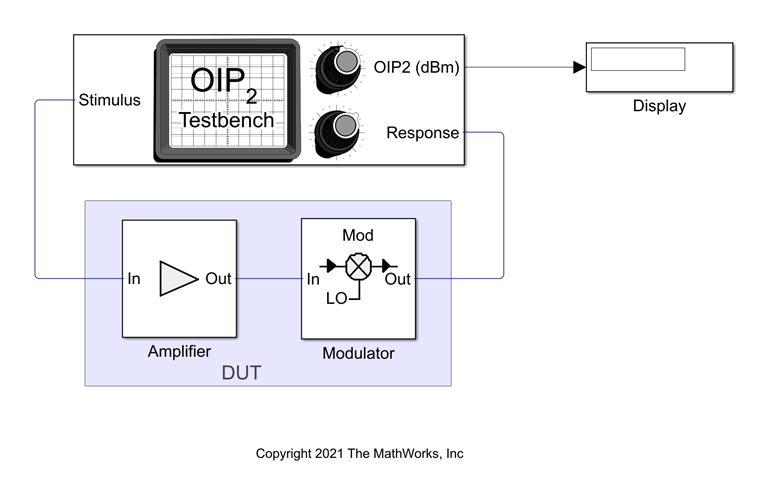
Set the parameters for DUT and the testbench.
Amplifier block:
Available power gain —
10dBIntercept points convention —
Input
Mixer block:
Available power gain —
5dBLocal oscillator frequency —
2.0GHzAdd Image Reject filter —
onIntercept points convention —
OutputIP2 —
32dBmFilter type —
HighpassImplementation —
Constant per carrierPassband edge frequency —
2.05GHz
OIP2 Testbench block:
Input frequency (Hz) —
2.1e9Output frequency (Hz) —
0.1e9Simulate noise (both stimulus and DUT internal) —
off
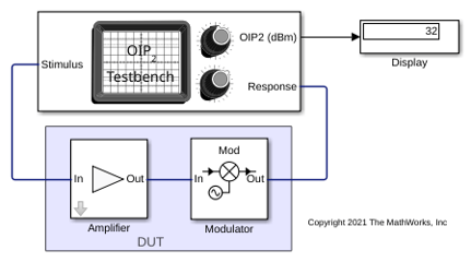
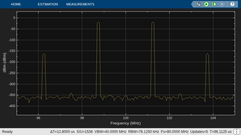
Run the model. You will see that the display shows an OIP2 value of 32 dBm since the OIP2 was specified only in the Mixer block.
See Also
OIP2 Testbench | OIP3 Testbench | IIP3 Testbench | IIP2 Testbench

