Configuring Angle-Dependent Behavior in the Angle-Based Rotational Domain
This example shows how to set up a custom mechanism with characteristics that depend on the instantaneous angle in an angle-based rotational network.
Key modeling steps in this example include:
Using a Rotational Motion Sensor (AB) block to measure the angle of a point in the system.
Using a PS Lookup Table to calculate a characteristic based on the angle.
Adjusting a block's behavior using the output from the PS Lookup Table.
In this example, a brake disc has a low spot over an 80-degree angle. When this low spot moves through the brake calipers, the normal force applied by the calipers on the brake disc decreases, leading to slower vehicle stopping compared to a brake disc with a uniform surface.
System Overview
Open the ConfiguringAngleDependentBrakeIrregularity model.
open_system('ConfiguringAngleDependentBrakeIrregularity');
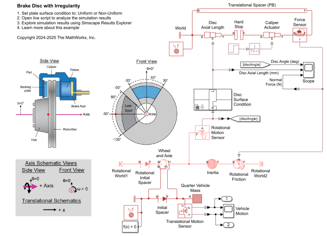
This system models a vehicle brake that consists of a disc passing through calipers. An angle-based rotational network models the rotating disc inertia and friction torque. A Rotational Motion Sensor block measures the disc's angle. The Disc Surface Condition subsystem adjusts the disc's axial length based on the sensed angle. The disc has a shorter axial length when the disc's low spot passes through the caliper contact area.
The two Rotational World blocks represent separate stationary points along the axis that have angles of 0 degrees: Rotational World1 is a reference point for the Initial Relative Angle block and Rotational World2 represents the non-rotating brake pad.
For details on setting directions in the angle-based rotational network and Wheel and Axle (AB-PB) block, see these examples:
A position-based translational network models the translation of the caliper piston and the disc's axial thickness. A caliper actuator controls the axial position of the caliper pad that clamps the brake disc. A Force Sensor block measures the force between the caliper and disc.
The force measured by the Force Sensor block serves as the normal force input signal to the Rotational Friction block in the rotational network. When the disc's axial length is reduced due to the low spot, the normal force- and thus the frictional torque- decreases.
A second position-based translational network models the vehicle's forward motion and includes a 500 kg mass, representing one-quarter of a passenger vehicle's mass. A Translational Motion Sensor block measures the vehicle's velocity and position.
In this scenario, the vehicle starts with a velocity of 50 km/hr, and the disc has an initial angle of -90 degrees. The caliper actuator begins clamping the brake disc after 1 second, causing the vehicle to decelerate.
Custom Mechanism
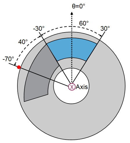
The brake disc typically has an axial length of 10 mm, but it has a low spot with an axial length of 7.5 mm. As the brake disc rotates, this low spot moves through the caliper contact area, which does not rotate and spans -30 degrees to 30 degrees. The low spot has an 80-degree angular span. This table highlights four key positions of the low spot on the disc as it aligns with the caliper contact area.
Disc Angle (deg) | Disc-Caliper State | Physical View |
-70 | Low spot (dark gray) starts to pass through the caliper contact area (blue). |
|
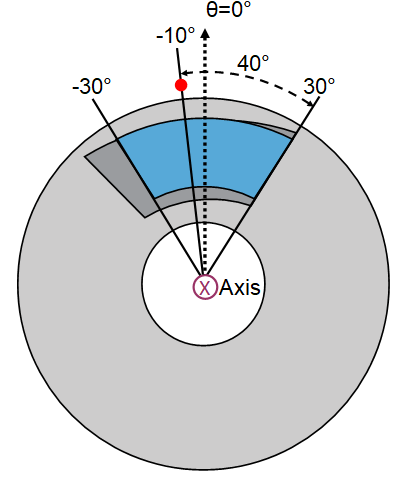
-10 | Low spot (dark gray) first spans the entire caliper contact area (blue). |
|
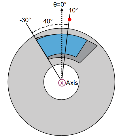
10 | Low spot (dark gray) stops spanning the entire caliper contact area (blue). |
|
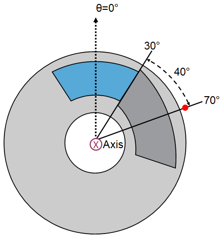
70 | Low spot (dark gray) has completely passed through the caliper contact area (blue). |
|
View the model for changing the disc's axial length between the calipers depending on the disc angle.
open_system('ConfiguringAngleDependentBrakeIrregularity/Disc Surface Condition/Nonuniform');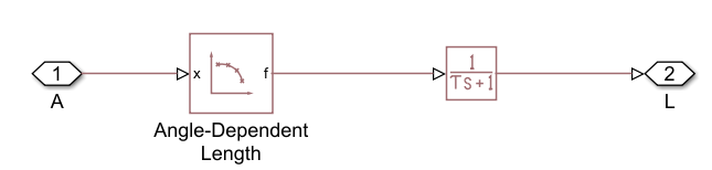
The input signal, A, represents the disc angle, while the output signal, L, is the disc axial length. The model includes a PS Lookup Table and a PS Transfer Function. The PS Lookup Table block, labeled "Angle-Dependent Length", outputs the disc's axial length as function of the disc angle. To capture all key regions, it is convenient to define the brake disc angles from -90 to 270 degrees, as shown in the Disc-Caliper States table. The Table grid vector parameter spans this range. The Rotational Motion Sensor block, which feeds into input signal A, wraps the sensed angle at -90 degrees, ensuring A always stays between -90 and 270 degrees. Consequently, the PS Lookup Table Extrapolation method does not affect the results.
The Table values in the PS Lookup Table are set so that the axial length linearly changes or remains constant in between the key disc angles shown in the Disc-Caliper States table. The PS Transfer Function smooths the changes of the disc's axial length, helping the numerical solver efficiency.
Simulate the System and View Results from Scopes
Simulate the model when the disc plate has a low spot.
set_param([bdroot '/Disc Surface Condition'], 'SurfaceType', 'Nonuniform')
open_system('ConfiguringAngleDependentBrakeIrregularity/Disc');
sim('ConfiguringAngleDependentBrakeIrregularity');
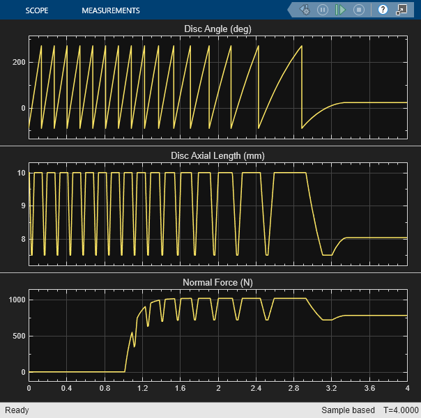
The disc starts at an initial angle of -90 degrees. During each revolution, the axial length of the disc in the caliper contact area varies between 7.5 mm and 10 mm. The caliper actuator begins clamping the disc plate after 1 second. The normal force exerted on the disc rises to a peak of just over 1000 N. When the low spot enters the caliper contact area, the normal force decreases to 720 N.
Compare the Performance of the Nonuniform and Uniform Disc Surfaces
The Disc Surface Condition subsystem is a variant subsystem. You can use its dialog box to switch the disc surface between two options: the nonuniform plate with a low spot and a uniform plate with a constant axial length.
Simulate the system with the nonuniform and uniform plates to evaluate their performance. Plot the vehicle's position and velocity over time for each plate condition to compare their effects on vehicle stopping distance.
close_system('ConfiguringAngleDependentBrakeIrregularity/Disc');

set_param('ConfiguringAngleDependentBrakeIrregularity/Disc Surface Condition', 'SurfaceType', 'Nonuniform')
sim('ConfiguringAngleDependentBrakeIrregularity');
tout_Nonuniform = tout;
yout_Nonuniform = yout;

set_param('ConfiguringAngleDependentBrakeIrregularity/Disc Surface Condition', 'SurfaceType', 'Uniform')
sim('ConfiguringAngleDependentBrakeIrregularity');
tout_Uniform = tout;
yout_Uniform = yout;

figure;
tiledlayout(2,1);
nexttile;
hold on
plot(tout_Nonuniform, yout_Nonuniform(:,1));
plot(tout_Uniform, yout_Uniform(:,1));
title('Vehicle Velocity versus Time');
ylabel('Velocity (km/hr)');
legend('Nonuniform Disc Surface', 'Uniform Disc Surface')
nexttile;
hold on
plot(tout_Nonuniform, yout_Nonuniform(:,2));
plot(tout_Uniform, yout_Uniform(:,2));
title('Vehicle Position versus Time');
ylabel('Position (m)');
The brake system with a uniform disc surface enables the vehicle to stop within 15.5 meters, taking 2.2 seconds after the caliper actuator is engaged at a time of 1 second. In contrast, the brake system with a nonuniform disc surface results in the vehicle stopping within 16.9 meters, taking 2.4 seconds after the caliper actuator is engaged. This change represents a 9% increase in both stopping distance and stopping time due to the disc surface irregularity.