Create ADXL343 Sensor Block to Read Acceleration Using IO Device Builder App
This example shows how to use the IO Device Builder app to create ADXL343 sensor to measure acceleration. In this example, the ADXL343 sensor values are retrieved by using the SPI bus requiring four wires (SCL, SDA, SDO and CS).
Note:
By default, communication libraries such as SPI, I2C, and Servo are included. For information on adding other libraries, see Working with Arduino Libraries in IO Device Builder.
The IO Device Builder app supports only Monitor & Tune (External mode) and Build, Deploy & Start options. Connected IO is not supported.
Prerequisites
Download and extract the following zip files from GitHub®.
ADXL343 drivers
Dependent files Adafruit Unified Sensor
Dependent files Adafruit_BusIO
Circuit Connections
To run this example, make these circuit connections.
For 5.0V LOGIC boards: Connect 5V on the Arduino® to VIN on the ADXL343.
For 3.3V LOGIC boards: connect 3.3V on the Arduino to VIN on the ADXL343.
Connect GND on the Arduino to GND on the ADXL343.
Connect SDO to MISO, SDA to MOSI, SCL to SCLK and CS to digital pin 10 from the sensor to Arduino.
Open the IO Device Builder App
To open the IO Device Builder app, perform these steps.
Start MATLAB® and then open / create a Simulink® model.
Go to Modeling > Model Settings to open the Configuration Parameters dialog box.
Open the Hardware Implementation pane, and select a Arduino board.
On the Hardware tab of the Simulink toolstrip, in Prepare section, under Design, choose IO Device Builder.

Select Working Directory and Add Third-Party Source Files
Once the Source files location page loads, select the working directory and add third-party source files.

On the Source files location page:
Click Select and select the working directory. In the working directory, the generated system object, along with the corresponding cpp and h files, and the model are located.
Click Add folder and add the folders you downloaded. Only the files present directly within the selected folder are included, and any files present within subfolders are excluded.
Click Next to continue.
Select Source Files

On the Source files page, select the required source files and then click Next to continue.
Specify Block Parameters

On the Block parameters page:
Specify the block name and add block description.
Add mask parameter with the name
accelRange,int8as Data type,3as initial value, andTunableas Type.Click Next to continue.
Select Outputs for the Block

On the Outputs page:
Add Output port as x,y and z as mentioned in driver file and set data type as
singleand Dimension as[1,1].Click Next to continue.
Select Inputs for the Block

On the Inputs page:
Remove inputs for the block, if any already added.
Click Next to continue.
Preview Block

On the Block image page, view the preview of the block with the inputs and outputs you added. Click Next to continue.
Generate System Object Files

The app displays the location of the System object file on the Generate page. Choose the Select to generate a C++ driver option, if you want to generate a C++ file.
Click Generate to generate the System object files.
Next Steps

On the Next Steps page, the generated files and recommended next actions are displayed. The generated files are created in a directory. This directory also includes a Dependencies folder that contains selected third-party source files. Simply copy these files and the folder to your desired location and integrate them into your Simulink project.
Click Finish on this page to complete the process. The generated .cpp file opens automatically.
Perform these steps.
1. Modify the generated .cpp file as shown below.
#include "C:\user\adxlSensor\adxl343.h"  // App generated header. Do not modify
#include "Wire.h"
#include "Adafruit_Sensor.h"
#include "Adafruit_ADXL343.h"
#include "Arduino.h"

#define ADXL343_CS 10
Adafruit_ADXL343 accel = Adafruit_ADXL343(ADXL343_CS, &SPI, 12345);
void setupFunctionadXLT2(int8_T * accelRange,int size_vector__1){
    while (!Serial);
       if(!accel.begin())
    {
        while(1);
    }
    accel.setRange(*accelRange);
}

void stepFunctionadXLT2(float * x,int size_vector_1,float * y,int size_vector_2,float * z,int size_vector_3){
    sensors_event_t event;
    accel.getEvent(&event);
    delay(10);
    *x=event.acceleration.x;
    *y=event.acceleration.y;
    *z=event.acceleration.z;
}
2. Assign the output to the selected output port.
3. Add the #include "Arduino.h" header and other required headers for the driver, as mentioned in ino example with the absolute address.
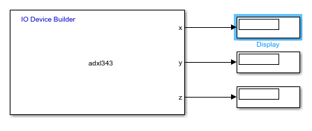
4. In the already opened Simulink model, add and connect Display blocks to the output ports.
5. In the Simulink model, navigate to Modeling > Model Settings and in the Configuration Parameters dialog box, click Hardware Implementation and then select an Arduino board.
A sample Simulink model is shown here.