Standard Servo Write
R2026bSet shaft position of standard servo motor to angle specified in degrees
Standard Servo Write block
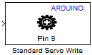
To add a block to a model, double-click the canvas and start typing the block name. Then, select the block from the list.
Libraries:
Simulink Support Package for Arduino Hardware /
Common
Description
Add-On Required: This feature requires the Simulink Support Package for Arduino Hardware add-on.
The Standard Servo Write block sets the shaft position of the servo motor
from 0 to 180 degrees depending on the input value sent
to the block on the Arduino® hardware pin.
You can run a Simulink® model containing Standard Servo Write block in Connected IO mode on Arduino boards.
Note
If you use the Standard Servo Write block along with the Serial Receive and Serial Transmit blocks in a Simulink model, use longer sample times to avoid overruns.
Maximum Number of Servo Blocks Allowed Per Simulink Model
The number of Servo blocks, Standard Servo Read, Standard Servo Write, and Continuous Servo Write, you can use in your Simulink model depends on the number of timers on your Arduino hardware board. Every timer on the Arduino board can support up to 12 Servo blocks.
For example, consider the Arduino Mega 2560/ADK board. The maximum number of servo
blocks that can be used per Simulink model is 48. If your Simulink model utilizes a total number of 48 Servo blocks and the board has 5 timers,
timer 5 supports the first set of 12 (1 to 12) Servo blocks. Similarly, timer 1 supports the
next set of 12 (13-24) Servo blocks, timer 3 supports the next set of 12 (25-36) Servo
blocks, and finally, timer 4 supports the last set of 12 (37-48) servo
blocks.
The Servo blocks are grouped as follows:
Set 1: Servo blocks 1 to 12
Set 2: Servo blocks 13 to 24
Set 3: Servo blocks 25 to 36
Set 4: Servo blocks 37 to 48
Set 5: Servo blocks 49 to 60
This table shows how to assign timers to Servo blocks depending on the Arduino board you are using. It also provides the maximum number of Servo blocks that you can use per Simulink model.
| Arduino/ Arduino Compatible Boards | Timer | Maximum Number of Servo Blocks per Simulink Model |
|---|---|---|
| Uno, Nano 3.0 | 1 | Set 1 |
| Mega 2560/ADK | 1 | Set 2 |
| 3 | Set 3 | |
| 4 | Set 4 | |
| 5 | Set 1 | |
| Leonardo, Robot Control Board, Robot Motor Board, Micro | 1 | Set 1 |
| MKR 1000, MKR WiFi 1010, MKR Zero | TC4 | Set 1 |
| Nano 33 IoT | TC4 | Set 1 |
| Due | TC3_CH0 | Set 1 |
| TC4_CH1 | Set 2 | |
| TC5_CH2 | Set 3 | |
| TC2_CH2 | Set 4 | |
| TC0_CH0 | Set 5 | |
| FSP Timer | Set 1 |
| PIT0 | Set 4 |
| PIT1 | ||
| PIT2 | ||
| PIT3 | ||
| 0 | Set 4 |
| 1 | ||
| 2 | ||
| 3 | ||
| 0 | Set 1 |
Ports
Input
Parameters
Version History
Introduced in R2012a

