Revolved Solid
Solid revolved element with geometry, inertia, and color

Libraries:
Simscape /
Multibody /
Body Elements
Description
The Revolved Solid block models the rotational sweep of a cross-section, with its geometric center coincident with the [0 0] coordinate on the cross-sectional xz-plane and its axis of revolution aligned with the reference frame z-axis.

By default, the block has only one reference frame that defines the position and
orientation of the solid. To create additional frames on the body, in the
Frames section, select the Create button
![]() .
.
You can use the block to model a single rigid body or create a compound rigid body by combining it with other solids that are rigidly connected and positioned using Rigid Transform blocks.
Compute Inertia Properties
You can compute the inertia properties of a solid, if you set the Inertia > Type parameter to
Calculate
                                        from Geometry
. This setting exposes the
Inertia button in the toolstrip of the Property Inspector. To
compute the inertia properties, click the Inertia button and the visualization pane displays
the computed values.
![]()
The block defines the center of mass in the reference frame of the solid and specifies the moments and products of inertia in the inertia frame of resolution, which aligns its axes with the reference frame and positions its origin at the center of mass of the solid.
Visualize Solid
The Property Inspector includes a visualization pane that provides instant visual feedback on the solid. Use the pane to check and adjust the shape and color of the solid. To inspect the solid from different angles, select a standard view, interact with the view selection cube or orientation triad, or rotate, pan, and zoom the display.
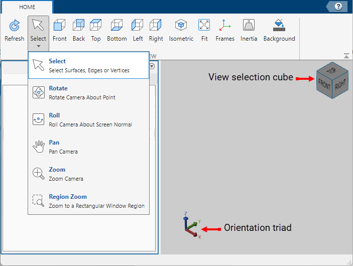
To view the latest changes to the solid geometry in the visualization pane, in the toolstrip, click Refresh. You can also display the frames on the solid and change the background color of the visualization pane by clicking Frames and Background in the toolstrip.
Examples
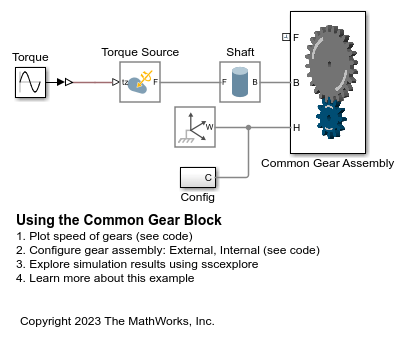
Using the Common Gear Block
Models a pair of gears with parallel axes. The assembly contains the two gears and all constraints required for the gear set. The assembly can be configured to model an external or internal gear set by adjusting parameters in the mask.
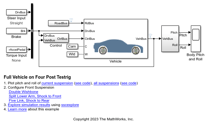
Full Vehicle on Four Post Testrig
Models a passenger vehicle on a four-post testrig. The posts move up and down to replicate the vertical movement of the wheels as it travels along a road. The simulation results and animation show the response of the vehicle body and suspension as it is subjected to the motions from the testrig. The roll and pitch of the vehicle body can be observed, and by varying the inputs wheel hop frequencies can be determined. The vehicle model can be configured to use different suspension types for the front suspension with different linkage combinations.
Limitations
On Mac, the visualization pane runs slow if the generated geometry has a large number of triangles or vertices. To mitigate this issue, you can decrease the number of points in the cross-section.
Ports
Frame
Geometry
Parameters
Geometry
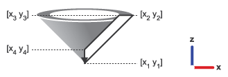
Cross-sectional shape specified as an [x z] coordinate matrix, where each row corresponding to a point on the cross-sectional profile. The coordinates specified must define a closed loop with no self-intersecting segments.
The coordinates must be arranged such that from one point to the next the solid region always lies to the left. The block revolves the cross-sectional shape specified about the reference frame z axis to obtain the revolved solid.
Type of revolution sweep to use. Use the default setting of
Full to revolve the cross-sectional shape
by the maximum 360 degrees. Select Custom to
revolve the cross-sectional shape by an angle.
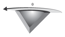
Angle of the rotational sweep associated with the revolution.
Dependencies
To enable this parameter, set Extent of
Revolution to
Custom.
Under the Export, select Convex Hull to generate a convex hull representation of the true geometry. This convex hull can be used for contacts by connecting the Spatial Contact Force block.
Inertia
Inertia parameterization to use. Select Point Mass to model a concentrated mass with negligible rotational inertia. Select Custom to model a distributed mass with the specified moments and products of inertia. The default setting, Calculate from Geometry, enables the block to automatically calculate the rotational inertia properties from the solid geometry and specified mass or mass density.
Parameter to use in inertia calculation. The block obtains the inertia tensor from the solid geometry and the parameter selected. Use Density if the material properties are known. Use Mass if the total solid mass if known.
Dependencies
To enable this parameter, set Type to Calculate
from Geometry.
Mass per unit volume of material. The value is a scalar with units of density and can be positive or negative. Specify a negative mass density to model the effects of a void or cavity in a solid body.
Dependencies
To enable this parameter, set:
Type to
Calculate from GeometryBased on to
Density
Total mass to attribute to the solid element. This parameter can be positive or negative. Use a negative value to capture the effect of a void or cavity in a compound body (one comprising multiple solids and inertias), being careful to ensure that the mass of the body is on the whole positive.
Dependencies
To enable this parameter, set Type to
Custom or Point Mass.
Alternatively, set Type to Calculate from
Geometry and then set Based on to
Mass.
Display of the calculated values of the solid mass properties—mass, center of mass, moments of inertia, and products of inertia. Click the Update button to calculate and display the mass properties of the solid. Click this button following any changes to the block parameters to ensure that the displayed values are still current.
The center of mass is resolved in the local reference frame of the solid. The moments and products of inertia are each resolved in the inertia frame of resolution—a frame whose axes are parallel to those of the reference frame but whose origin coincides with the solid center of mass.
Dependencies
The option to calculate and display the mass properties is active
when the Inertia > Type block parameter is set to Calculate from
Geometry.
Graphic
Type of the visual representation of the solid, specified as From Geometry, Marker, or None. Set the parameter to From Geometry to show the visual representation of the solid. Set the parameter to Marker to represent the solid as a marker. Set the parameter to None to hide the solid in the model visualization.
Shape of the marker by means of which to visualize the solid. The motion of the marker reflects the motion of the solid itself.
Dependencies
To enable this parameter, set Type to Marker.
Width of the marker in pixels. This width does not scale with zoom level. Note that the apparent size of the marker depends partly on screen resolution, with higher resolutions packing more pixels per unit length, and therefore producing smaller icons.
Dependencies
To enable this parameter, set Type to Marker.
Color of the graphic under direct white light, specified as an [R G B] or [R G B A] vector on a 0–1 scale. An optional fourth element (A) specifies the color opacity on a scale of 0–1. Omitting the opacity element is equivalent to specifying a value of 1.
Dependencies
To enable this parameter, set Type to From
Geometry or Marker.
Color of the light due to diffuse reflection, specified as an [R,G,B] or [R,G,B,A] vector with values in the range of 0 to 1. The vector can be a row or column vector. The optional fourth element specifies the color opacity. Omitting the opacity element is equivalent to specifying a value of 1.
The diffuse color reflects the main color of the rendered solid and provides shading that gives the rendered object a three-dimensional appearance.
Dependencies
To enable this parameter, set:
Type to
From GeometryorMarker.Visual Properties to
Advanced.
Color of the light due to specular reflection, specified as an [R,G,B] or [R,G,B,A] vector with values in the range of 0 to 1. The vector can be a row or column vector. The optional fourth element specifies the color opacity. Omitting the opacity element is equivalent to specifying a value of 1. This parameter changes the color of the specular highlight, which is the bright spot on the rendered solid due to the reflection of the light from the light source.
Dependencies
To enable this parameter, set:
Type to
From GeometryorMarker.Visual Properties to
Advanced.
Color due to self illumination, specified as an [R,G,B] or [R,G,B,A] vector in the range of 0 to 1. The vector can be a row or column vector. The optional fourth element specifies the color opacity. Omitting the opacity element is equivalent to specifying a value of 1.
The emission color is color that does not come from any external source, and therefore seems to be emitted by the solid itself. When a solid has an emissive color, the solid can be seen even if there is no external light source.
Dependencies
To enable this parameter, set:
Type to
From GeometryorMarker.Visual Properties to
Advanced.
Frames
Select to expose the R port.
Click the Create button ![]() to open a pane for creating a new
body-attached frame. In this pane, you can specify the name, origin, and
orientation for the frame.
to open a pane for creating a new
body-attached frame. In this pane, you can specify the name, origin, and
orientation for the frame.
To name the custom frame, click the text field of the Frame Name parameter. The name identifies the corresponding port on the solid block and in the tree view pane of the Multibody Explorer.
To select the Frame Origin of the custom frame, use one of the following methods:
At Reference Frame Origin: Make the new frame origin coincident with the origin of the reference frame of the solid.
At Center of Mass: Make the new frame origin coincident with the center of mass of the solid.
Based on Geometric Feature: Make the new frame origin coincident with the center of the selected feature. Valid features include surfaces, lines, and points. Select a feature from the visualization pane, then click Use Selected Feature to confirm the location of the origin. The name of the origin location appears in the field below this option.
To define the orientation of the custom frame, under the Frame Axes section, select the Primary Axis and Secondary Axis of the custom frame and then specify their directions.
Use the following methods to select a vector for specifying the directions of the primary and secondary axes. The primary axis is parallel to the selected vector and constrains the remaining two axes to its normal plane. The secondary axis is parallel to the projection of the selected vector onto the normal plane.
Along Reference Frame Axis: Selects an axis of the reference frame of the solid.
Along Principal Inertia Axis: Selects an axis of the principal inertia axis of the solid.
Based on Geometric Feature: Selects the vector associated with the chosen geometry feature of the solid. Valid features include surfaces and lines. The corresponding vector is indicated by a white arrow in the visualization pane. You can select a feature from the visualization pane and then click Use Selected Feature to confirm the selection. The name of the selected feature appears in the field below this option.
Frames that you have created. N is a unique identifying number for each
custom frame.
Click the text field to edit the name of an existing custom frame.
Click the Edit button
 to edit other aspects of the
custom frame, such as origin and axes.
to edit other aspects of the
custom frame, such as origin and axes.Click the Delete button
 to delete the custom
frame.
to delete the custom
frame.
Dependencies
To enable this parameter, create a frame by clicking New Frame.
Extended Capabilities
Version History
Introduced in R2019b