Import a CAD Assembly Model
You import a CAD assembly model into Simscape™ Multibody™ software using the smimport function. The function parses an XML multibody description file and automatically generates the corresponding model. Geometry files accompanying the multibody description file format provide the body geometries for visualization purposes.
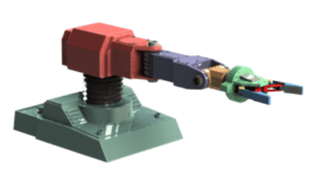
This example shows how to generate a robot model from a XML file using the smimport function. The example is based on the Robot.xml and a set of part geometry files.
To use the XML and geometry files, open this example, and then add the supporting files to the search path for the current MATLAB® session:
addpath(genpath("ImportedCADModelSupport"))Import the Model with Default Name
Import a CAD model of a robotic arm and store it in memory as the default name. You can change the name later. As the model is in XML format, you can omit the extension in its name.
smimport("Robot");Simscape Multibody generates the model described in the Robot.xml file using the default smimport function settings.
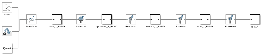
The blocks in the generated model are parameterized in terms of MATLAB variables. The numerical values of these variables are defined in a data file that is named Robot_DataFile.m and stored in the same active folder as the generated model.
Import the Model with Custom Name
Alternatively, you can import the CAD model of the robotic arm and save it in the current folder with a custom name. Name the model as Robotto and the parameter data file as Robottos_Data_File.
smimport("Robot","ModelName","Robotto",...
"DataFileName","Robottos_Data_File");
Update the Imported Model
Regenerate the data file for the imported CAD model of the robotic arm. To avoid overwriting the original data file, name the new file Robottos_New_Data_File.
smimport("Robot","ImportMode","dataFile","DataFileName",...
"Robottos_New_Data_File","PriorDataFile","Robottos_Data_File");
Point the imported model to the new data file and reinitialize the model workspace.
hws = get_param(bdroot,"modelworkspace");
hws.DataSource = "MATLAB File";
hws.FileName = "Robottos_New_Data_File";
hws.reload
To do the same using Model Explorer, first, select Modeling > Design > Model Workspace to open the Model Explorer. Next, in the Model Hierarchy of the Model Explorer, left click Model Workspace. In the Model Workspace pane, enter Robottos_New_Data_File.m in the File Name parameter and click Reinitialize from Source button to apply the change.
Visualize the Model
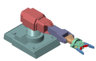
Update the diagram to visualize the model. In the Modeling tab, click Update Model. Mechanics Explorer opens with a static visualization of the robotic arm model in its initial configuration.
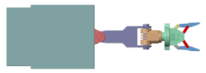
The default view convention in Mechanics Explorer differs from that in the CAD application used to create the original assembly model. Mechanics Explorer uses a Z-axis-up view convention while the CAD application uses a Y-axis-up view convention.
Change the view convention from the Mechanics Explorer toolstrip by setting the View convention parameter to Y up (XY Front). Then, select a standard view from the View > Standard Views menu to apply the new view convention.
Check the Model
Check the imported model for unexpected rigid connections between bodies. Simscape Multibody software replaces unsupported CAD constraints with rigid connections that may appear as direct frame connection lines, Rigid Transform blocks, or Weld Joint blocks.
A warning message in the MATLAB command window identifies the bodies and connection frames affected by the unsupported constraints. Replace the artificial rigid connections between the bodies with suitable Joint, Constraint, or Gear blocks from the Simscape Multibody library.
Update the block diagram to rule out model assembly errors. Run simulation to ensure the model dynamics are as expected. If you update the source CAD assembly model, you can generate an updated data file directly from a new multibody description file.
Simulate the Model
Try to simulate the model. Because the robotic arm lacks a control system, it simply flails under gravity. You can use Simulink® blocks to create the control system needed to guide the robotic arm motion. A control system would convert motion sensing outputs into actuation inputs at the various joints. You can expose the sensing and actuation ports from the joint block dialog boxes.
See Also
Related Topics
You can also select a web site from the following list:
Americas
- América Latina (Español)
- Canada (English)
- United States (English)
Europe
- Belgium (English)
- Denmark (English)
- Deutschland (Deutsch)
- España (Español)
- Finland (English)
- France (Français)
- Ireland (English)
- Italia (Italiano)
- Luxembourg (English)
- Netherlands (English)
- Norway (English)
- Österreich (Deutsch)
- Portugal (English)
- Sweden (English)
- Switzerland
- United Kingdom (English)