AM Radio Receiver
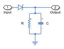
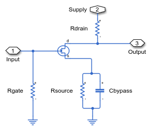
This example shows a simplified AM radio receiver. A single tone signal at 2kHz is transmitted with a carrier frequency of 600kHz. The variable capacitor, Cres, in the resonant circuit is used in order to sweep through a certain frequency span. When the resonance passes through 600kHz, the signal is picked up and amplified by a two-stage Class A RF power amplifier. The signal is finally extracted by a diode detector, where it would normally be passed on to an audio amplifier (not included here). The Scope displays the final output, the value of the resonant capacitance, and the received and amplified signals.
Model

Diode Detector Subsystem

Two-Stage Amplifier Subsystem

Class A Stage 1 Subsystem

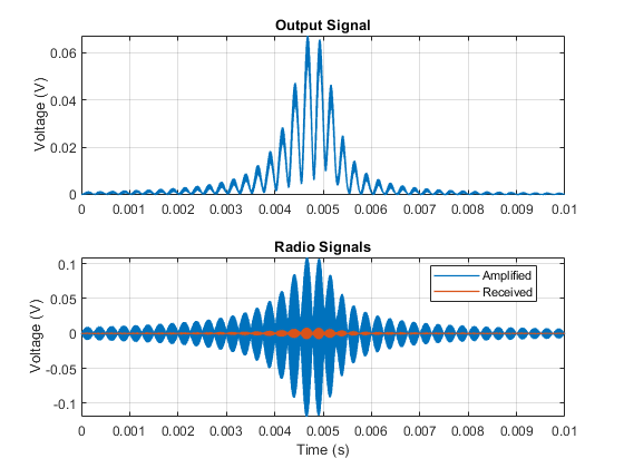
Simulation Results from Simscape Logging
The plots below shows received, amplified, and output signals in the radio receiver. As the resonance in the resonant circuit passes through 600kHz, the signal is picked up and amplified by a two-stage Class A RF power amplifier.
