Fourth-Order Sallen-Key Lowpass Filter
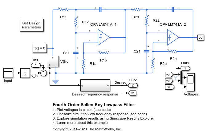
This example shows an implementation of a fourth-order Sallen-Key low-pass filter using Operational Amplifiers (OPAs). The filter design parameters, cut-off frequency (f1) and DC gain (K), are specified by double-clicking on the Set Design Parameters block. Pass-band ripple is predefined to be 1dB using a Chebyshev response. The block mask calls a function which sets the parameter values in the model workspace.
This model can be used to generate the filter frequency response. In the ideal case, the gain is equal to 20*log10(K) dB at DC, 20*log(K) at the cut-off frequency, maximum value 20*log10(K) + 1, and -24dB/octave attenuation at high frequency.
Model

Simulation Results from Simscape Logging
The plot below shows the response of the filter to a brief voltage pulse. This response can be analyzed numerically to determine the frequency response of the filter. The result from the circuit is compared with the result from a transfer function which was specified using the desired frequency response behavior, and we see that the results match nearly perfectly.

Frequency Response
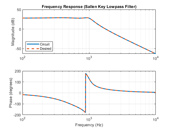
The plot below shows the frequency response of the filter. The gain is equal to 20*log10(K) dB at DC, 20*log(K) at the cut-off frequency, maximum value 20*log10(K) + 1, and -24dB/octave attenuation at high frequency. The frequency response obtained from the circuit nearly perfectly matches the results from a transfer function specified using the desired frequency response behavior.
