Phase-Locked Loop
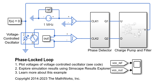
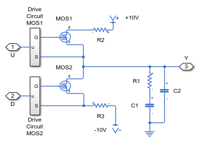
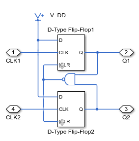
This model shows how to model a phase-locked loop. The charge pump and filter are modeled using discrete analog components whereas the oscillator is represented as behavioral component using the Simscape™ Electrical™ Voltage-Controlled Oscillator block. The D-type flip-flops in the phase detector are represented in a simplified form using Simulink® blocks to define the behavior, and electrical components are used just at the interface. Non-zero initial conditions are applied to C1 and C2 in order to start the VCO out of phase and test the tracking ability.
Model

Charge Pump and Filter Subsystem

Phase Detector Subsystem

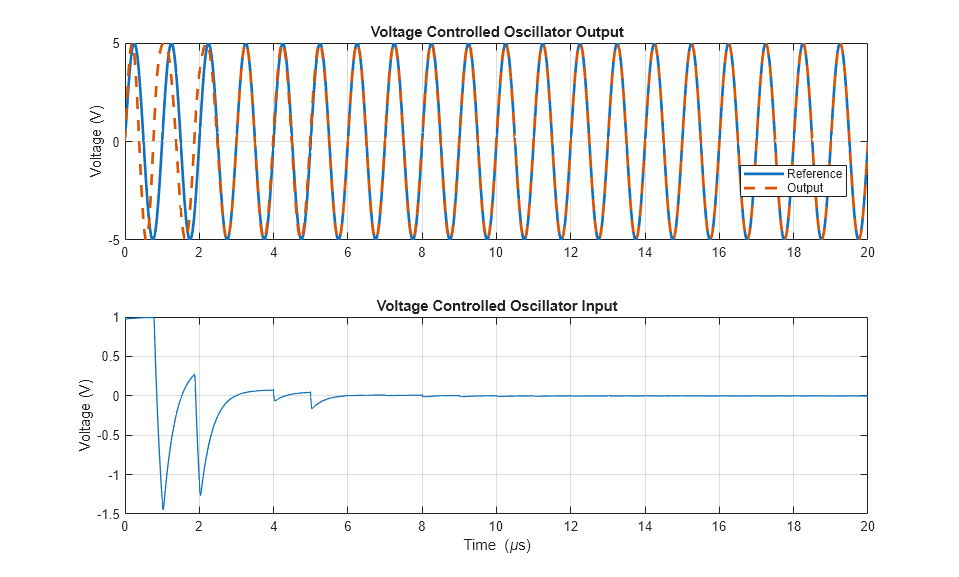
Simulation Results from Simscape Logging
The plot below shows the reference and output voltage for the voltage controlled oscillator within a phase locked loop.
