Analog to Digital Converter
Convert analog signal on ADC input pin to digital signal
Libraries:
STM32 Microcontroller Blockset /
STM32F1xx Based Boards
STM32 Microcontroller Blockset /
STM32F2xx Based Boards
STM32 Microcontroller Blockset /
STM32F3xx Based Boards
STM32 Microcontroller Blockset /
STM32F4xx Based Boards
STM32 Microcontroller Blockset /
STM32F7xx Based Boards
STM32 Microcontroller Blockset /
STM32G0xx Based Boards
STM32 Microcontroller Blockset /
STM32G4xx Based Boards
STM32 Microcontroller Blockset /
STM32H5xx Based Boards
STM32 Microcontroller Blockset /
STM32H7xx Based Boards
STM32 Microcontroller Blockset /
STM32L4xx Based Boards
STM32 Microcontroller Blockset /
STM32L5xx Based Boards
STM32 Microcontroller Blockset /
STM32U5xx Based Boards
STM32 Microcontroller Blockset /
STM32WBxx Based Boards
Description
Measure the voltage of an analog pin relative to the analog input reference voltage on the STM32F4-Discovery™ board. The block output emits analog voltage in varying ranges based on the conversion resolution selected for the ADC in Configuration parameters > Hardware Implementation > Hardware board > Target hardware resources > ADCx > Conversion resolution.
Note
The conversion time for ADC channels is configured based on the ADC resolution and sample time specified in Configuration parameters > Hardware Implementation > Hardware board > Target hardware resources > ADCx.
For example: When you select 12-bits as resolution for ADC1, the block output emits the analog voltage ranging from 0 to 4095. If the measured voltage equals the ground voltage, the block output emits 0. If the measured voltage equals the analog reference voltage, the block output emits 4095.
You can read up to 16 channels of analog signals from ADC1, ADC2, or ADC3 modules in single, continuous, scan, or discontinuous modes.
The table shows the analog pins corresponding to the channels of the ADC modules that can use these pins to measure the voltage.
For example, ADC modules 1, 2, and 3 that corresponds to channel 12 can use the PC2 pin to measure the voltage. Here, PC2 refers to pin 2 on port C.

Examples
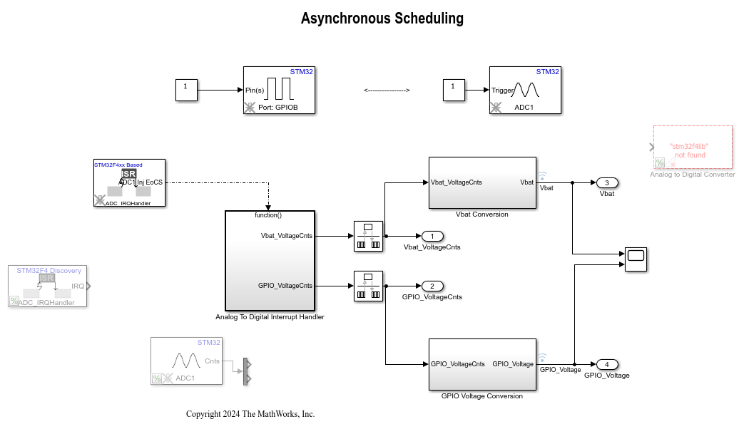
Asynchronous Scheduling for STM32F4-Discovery Board
Model asynchronous scheduling using the Hardware Interrupt block for the STMicroelectronics® STM32F4xx processor board using Asynchronous Scheduling for STM32F4-Discovery Board using STM32™ Microcontroller Blockset.
Ports
Input
Output
Parameters
Extended Capabilities
Version History
Introduced in R2013b