MDF File Logging on SD Card for STMicroelectronics STM32 Processors
This example shows you how to perform MDF-file logging using Simulink® model on a Micro SD card mounted on an STMicroelectronics® STM32 processor based board. Generate code that logs signals and outputs to an ASAM Measurement Data Format (MDF) file.
The STM32 product supports logging of signals from Simulink models. These signals are logged in an MDF file on a Micro SD card mounted on an STM32 processor board.
Signal logging enables you to monitor the signal behavior and to perform any historical analysis of the data. The data is saved in the format specified by the MDF standard and does not directly map to MATLAB® data formats.
You can log signals if:
Signals at the top level of the model are logged automatically.
Signals explicitly marked for logging in the model are also logged.
This example provides you with the workflow to enable MDF-file logging and obtain the MDF-file on a Micro SD card mounted on an STM32 processor board.
These STMicroelectronics® STM32 boards support MDF-file logging to a Micro SD card:
STM32F2xx
STM32F4xx
STM32F7xx
STM32H7xx
STM32L4xx
Required Hardware
To run this example, you need the following hardware:
STMicroelectronics STM32 board
External SD card interface
Micro SD card
Hardware Connection (For External SD Card Interface)
For external SD card interface, based on SD protocol, the CMD, CLK, D0-3,Vcc, GND,CD pins are to be connected to corresponding pins of STM32 board.
Connect VCC and GND pins to appropriate supply and ground.
Prepare the Connection and Configure a Simulink Model for MDF-File Logging
The MDF-file logging needs to be configured on the Simulink model so that the selected signals are logged on the Micro SD card on the STM32 processor board.
Insert the Micro SD card in the slot provided on the board.
Open the
GettingStartedExampleMDFFileLoggingmodel. This Simulink model is pre-configured with MDF-File logging enabled. In this example, signals are logged using outports and by marking signals to log.
modelName = 'GettingStartedExampleMDFFileLogging';
open_system(modelName)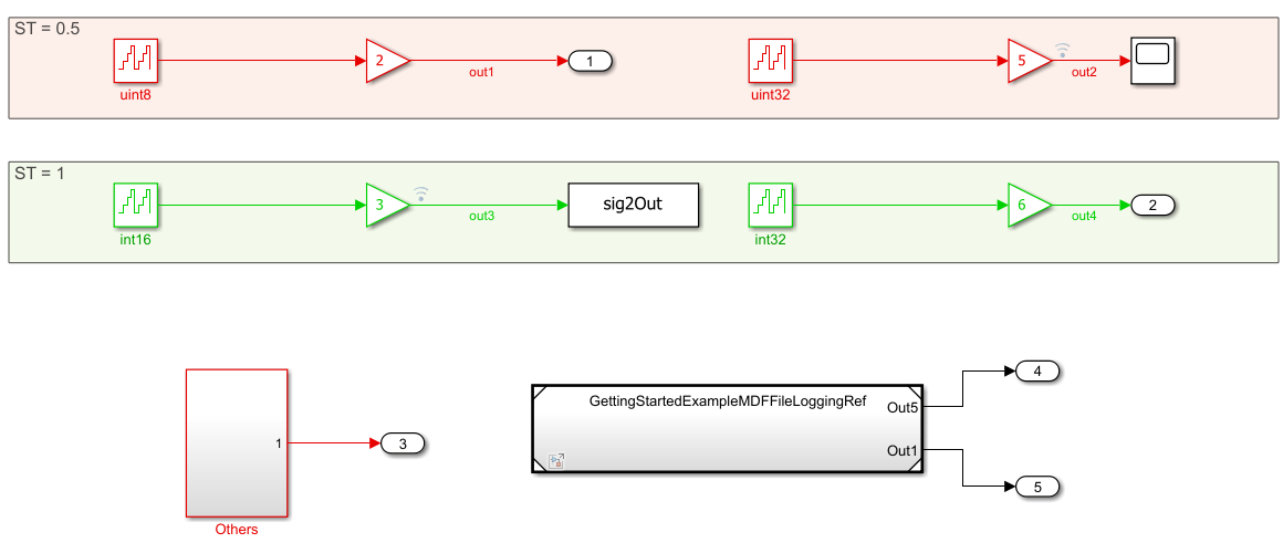
The model contains Outport, ToWorkspace, Subsystem blocks and Reference model to showcase the user what signals are logged and what are not. Follow the Log signals to MDF file (Simulink Coder) document to understand what signals are logged.
Configure Model to Enable MDF File Logging
To save signals to MDF-file(s) on an SD card, specify the target hardware details.
1. In your model window, open the Configuration Parameters dialog box, go to the Hardware Implementation pane, and select the name of the target hardware from the Hardware board list.

2. In the Hardware board settings pane, expand Target hardware resources and select SD card logging.
3. Select Enable file logging for SD card.
4. From the SD card logging type drop-down list, select MDF.
5. From the SD card logging interface drop-down list, select the required interface. The default values vary based on the Hardware board selected.
5. To verify the status of logging through GPIO, select the Enable logging status on GPIO option and then select the GPIO group and pin values from the drop-down lists.
6. Click Apply and OK to save your changes.
Configure IOC to Enable SD Card Logging
To save signals on an SD card, following need to be configured in IOC.
Configure SD Card Interface
1. Select the Mode as SD x bit xxxx for the interface mentioned in the model configuration settings.
2. Provide a clock divide factor such that the clock to the peripheral is 187kHz and 24MHz. Also sometimes the SD card logging may not work for smaller values of divide factor. So in that scenario, increase the clock divide factor. A clock factor of 10 can be taken as rough value to start with.

Configure FATFS
Select the Mode as SD Card for FATFS option in Middleware.
Enable the Use Long Filename so that there is no restriction on characters in file name.
Select a GPIO which is connected to SD detect pin on the SD card daughter board as GPIO Input.

Enable GPIO Logging Status Output
Select GPIO for enabling the logging status as GPIO output. A user LED is recommended for visual cue about the logging status.
Configuring Signals to Log
The model logs selected signals to an MDF file during simulation or execution on hardware. Signals are logged using either of the following mechanisms:
Signals at the top level of the model are logged automatically.
Signals explicitly marked for logging in the model are also logged.
Configure Model Stop Time
On the Modeling tab, enter a value for the stop time. This is the duration for which the signal is logged. However, the model continues to run on the hardware and it is not affected by the time specified.
For example, in the GettingStartedExampleMDFFileLogging, the stop time is 10. The signals will be logged for 10 seconds. If the stop time is Inf, the signal will be logged till the Micro SD card is full or the board is disconnected.
Deploy the Model on STM32 Discovery Board and View the MDF files
After the Simulink model is configured for MDF-file logging, you can deploy the model on the connected STM32 processor board and view the MDF-file(s) created on the Micro SD card.
1. In the Simulink model, go to Hardware tab and click Build, Deploy & Start. The build process for the model starts and it is deployed on the STM32 processor board. On successful deployment of the model, the LED on the board starts blinking.

2. To view the logged MDF-files, remove the Micro SD card from the board after the simulation time, and insert the card on your computer.
If the deployment of the model was successful, at least one MDF-file will be generated on the Micro SD card.
Viewing the MDF-file Data
You can view and analyze logged MDF data using Simulink Data Inspector.
To visualize MDF data interactively, import the MDF file into Simulink Data Inspector. Use the import workflow described in Import Data from Workspace or File into Simulation Data Inspector - MATLAB & Simulink to load MDF files and inspect logged signals.
To export logged data to a MAT-file for offline analysis or scripting, follow the workflow described in Save and Share Simulation Data Inspector Data and Views.
For automated or custom analysis, you can access MDF files programmatically using Vehicle Network Toolbox APIs. For more information, see MDF Files - MATLAB & Simulink.
Note: The achievable logging sample rate depends on multiple factors, including the target hardware, SD card performance, model complexity, and the number of signals being logged. Higher logging rates may result in data loss depending on these conditions.
The generated MDF file uses the same base name as the model. On subsequent runs, additional MDF files are created with an incremented run count appended to the file name.
Copyright 2026The MathWorks, Inc.