Totem-Pole Boost PFC With Inrush Current Limiter
This example shows how to model, simulate, and deploy a digital control algorithm for a totem-pole power factor correction (PFC) converter with an inrush current limiter (ICL).
The example shows how to:
Model and simulate a Totem-pole PFC converter with an inrush current limiter.
Validate closed-loop voltage and current control.
Generate and deploy optimized C code to an STM32 microcontroller.
Apply Model-Based Design techniques for power-conversion applications.
In this example, the totem-pole converter replaces the conventional diode bridge with controlled thyristors, enabling precise triggering and soft charging of the DC bus during startup.
Required Hardware
To run this example on hardware, you need:
Micro-USB cable for ST-LINK MB1441/MB1440 debugger and programmer. For more information, see STLINK-V3SET.
STEVAL-DPSTPFC1 Totem-pole PFC board with inrush current limiter
Resistive load bank
Voltage and current probes for measurement
Oscilloscope (to measure DC bus voltage, AC line input voltage, and AC line input current)
Model Overview
open_system("STM32_TotemPoleBoostPFC")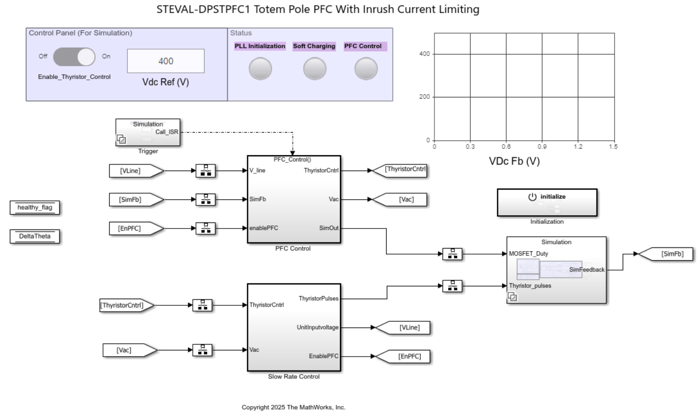
The model used in this example implements:
Power Stage Subsystem
Implements the totem-pole boost converter and inrush current limiting circuitry using Simscape Electrical components. This subsystem models the electrical behavior of the converter hardware.
Control Subsystem
Implements the digital control algorithms, including:
Current control loop
Voltage control loop
Soft-start and inrush current limiting logic
PWM generation
This subsystem is configured for code generation and deployment to the STM32 microcontroller.
Hardware Interface Subsystem
Maps controller signals to STM32 peripherals such as ADCs, PWM outputs, and timers, ensuring that the generated code interfaces correctly with the target hardware.
Verify Converter Behavior in Simulation
Simulate the model to examine converter behavior, including:
DC bus soft-charging during startup
Input-current shaping
Total harmonic distortion (THD)
Output-voltage regulation
Simulation enables verification of control behavior before deploying to hardware.
Configure Hardware Connections
Before deploying to hardware:
To avoid uncontrolled inrush events, load firmware before you power the evaluation board.
Verify wiring and jumper settings according to the STEVAL-DPSTPFC1 Hardware User Guide.
Ensure that you configure the model for the correct STM32 hardware board. Modify parameters in the
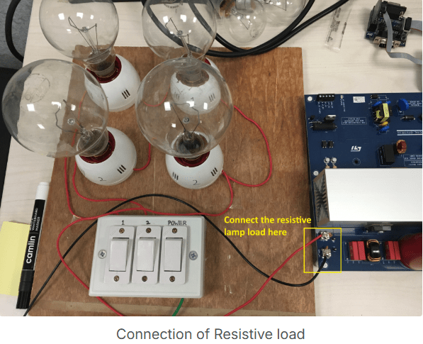
TotemPoleBoostPFC_data.mfile as needed for your model configuration.Ensure that a resistive load is connected at the DC link, as shown in the figure.
Build and Program Controller
Verify hardware connections, probe placement, and board configuration.
Ensure that the evaluation board is powered off before programming.
In Simulink®, click Build, Start, and Deploy to generate code and program the STM32 controller by using the ST-LINK programmer.
Keep the mains supply switched off during programming.
Power the control card from an external low-voltage supply only.
After programming completes disconnect the ST-LINK USB cable from the PC.
Note: Do not apply mains voltage until you complete post-deployment checks.
Post-Deployment Power-Up
Connect a resistive load across the DC bus.
Turn on the AC mains supply.
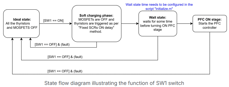
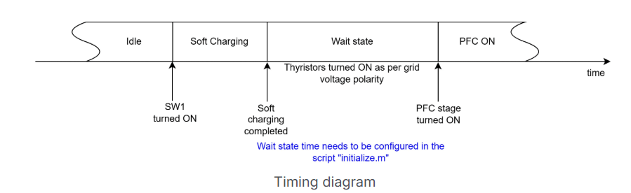
Set SW1 = 1 on the hardware to initiate the startup sequence. This action triggers the soft-charging stage followed by activation of the PFC control loop.
Verify Converter Performance
Use an oscilloscope to verify converter performance. The waveforms captured on a oscilloscope allow you to analyze both steady-state and transient behavior.
Verify the following:
Measure key electrical signals on the hardware to verify that the deployed controller operates as expected. Observe the DC bus voltage during steady-state operation to confirm that it tracks and regulates to the configured reference value. The measured waveform should show minimal overshoot and steady regulation once the startup sequence completes, indicating correct voltage-loop behavior.
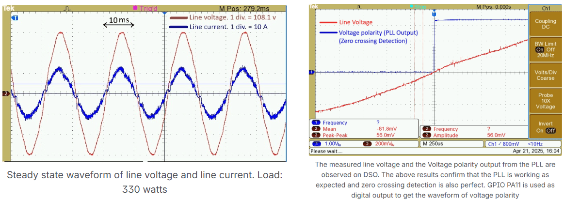
Next, observe the AC line voltage and line current simultaneously. The line current waveform should be sinusoidal and closely aligned with the line voltage, demonstrating near-unity power factor operation. This behavior confirms that the PFC control algorithm is shaping the input current correctly.
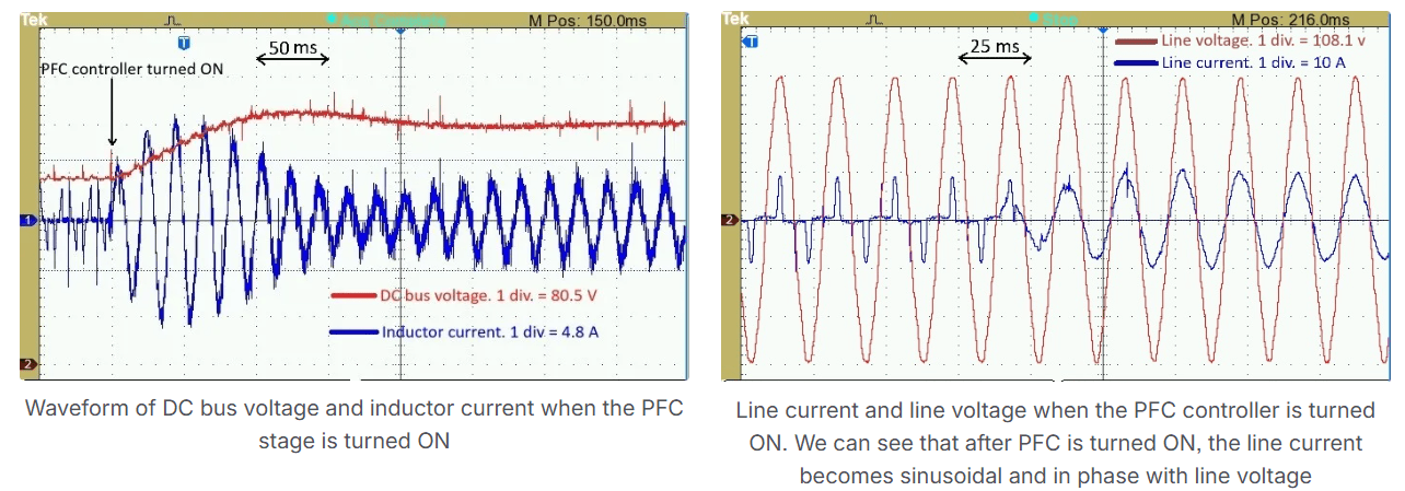
During startup, monitor the input current to verify the effectiveness of the inrush current limiter. The measured waveform should show a smooth, controlled rise in current, without large transients or abrupt spikes, as the DC bus charges. This behavior confirms that the soft-start and inrush current limiting logic operates as intended.
Finally, verify stable operation of the PFC stage under the applied resistive load. The output voltage should remain regulated while the input current maintains its expected shape, indicating that the controller sustains stable operation across the load conditions used in this example.