Contenuto principale

Anti-Lock Brake System

R2026b

Anti-lock brake system (ABS) controller

Since R2026b

  • Anti-Lock Brake System block

Libraries:
Vehicle Dynamics Blockset / Control

Description

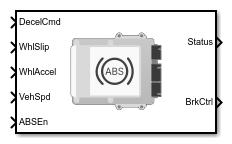
The Anti-Lock Brake System block implements an anti-lock braking system (ABS) controller that uses driver commands in conjunction with vehicle and wheel states to calculate the normalized brake control signal for each wheel. The block outputs this dimensionless signal in the range [0,1]. This signal represents the commanded braking action applied outside the block by downstream brake components to prevent wheel lock-up during braking.

The ABS controller independently modulates the braking action at each wheel to prevent sustained wheel lock-up during braking events. By operating each wheel near its optimal slip ratio, the controller maximizes available longitudinal tire force, thereby reducing stopping distance while preserving the capacity of the tire to generate lateral force. In addition to longitudinal performance, the ABS controller supports overall vehicle stability by maintaining lateral (yaw) authority and supporting sufficient steering capability throughout the braking maneuver.

The Anti-Lock Brake System block meets the performance criteria defined by SAE J2536, including:

  • Wheel lock-up prevention

  • Acceptable stopping distance

  • Maintenance of vehicle ability to steer

State Estimation

This block computes estimated wheel states, including wheel slip ratio and wheel rotational acceleration, and provides these signals for use by the core control algorithm during all controller operating phases.

Wheel Slip Ratio Estimation

The wheel speed, ω, and vehicle speed, v, are used to estimate the slip ratio, λ, using this formula.

λ=ω∗R−vmax(|v|,|ω*R|)

The wheel loaded radius, R, is used to convert angular wheel speed to linear wheel speed. Depending on which tire model you use with this block, you need to enter the correct wheel loaded radius and slip ratio that corresponds to the tire. The estimated slip ratio ranges from –1 to 1, where –1 indicates a fully locked wheel and 1 indicates a fully spinning wheel. In this convention, slip is negative during braking because the wheel rotates more slowly than the vehicle speed.

Wheel Acceleration Estimation

This method estimates wheel rotational acceleration, a, by applying a discrete‑time derivative to the wheel rotational speed signal.

Control Strategy

The Anti-Lock Brake System block operates using a four‑phase control strategy based on wheel‑behavior characteristics. When braking is commanded above a certain vehicle speed and excessive wheel slip is detected, ABS control is initiated, triggering the system to enter Phase 1 of the control sequence shown in the flow chart. In this context, p is the rate of change of the normalized braking command. ABS remains active until the vehicle speed decreases below a minimum threshold or the braking command is less than the deceleration threshold. These phases are described in detail in the table.

PhaseDescriptionPhase TransitionEntry ConditionExit Condition
ABS ActivationThe ABS controller is activated to enter the four-phase control strategy.The system enters Phase 1 upon activation.

All must be met to activate ABS control:

λij<λt

v>vt

Pd>0

Af==true

Exits ABS control if any is met:

v<vt

Pd<Pdt

Af==false

Pc≤Pct

Phase 1

Release: The wheel experiences rapid deceleration, indicating an imminent lock-up, and its slip ratio falls below the lower slip ratio threshold. To prevent the lock-up, the system decreases the brake command rapidly, allowing the slip ratio to return to the controlled range and enabling the wheel to regain rotational speed.

The system moves from excessive slip to recovering.

λij<λt

All must be met to exit:

λij≥λt

aij≥at1

Phase 2Hold: The slip ratio increases above the lower slip threshold and the wheel acceleration increases. The brake command is held constant and the wheel is stabilized.The system moves from recovering to stable.

All must be met to enter:

λij≥λt

aij≥at1

All must be met to exit:

λij≤0

λij≥λt

aij<at1

Phase 3Mild Increase: If excessive wheel acceleration occurs during Phase 2, the brake command increases slightly, and Phase 2 is re-entered. This process is iterative until the wheel is finally stabilized.Excessive wheel acceleration moves the system into this phase and recovering acceleration returns the system to Phase 2.

aij≥at2

All must be met to exit:

aij<at2

λij≤0

Phase 4Rapid Increase: The wheel behavior is in the stable region. The brake command can be maintained or increased to maximize braking force and to increase the magnitude of the wheel slip ratio. Phase 1 is triggered again when the slip ratio moves outside the threshold.The system moves from stable to excessive slip, and ABS control can proceed iteratively.

All must be met to enter:

λij≤0

λij≥λt

aij<at1

λij<λt

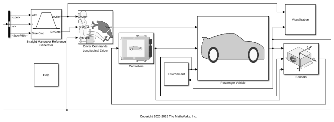
This figure illustrates the system phases and response under ABS control when run using the Braking Test Reference Application. The model in this example uses 0.32 for the wheel loaded radius and –0.05 for the target wheel slip. From top to bottom, the plots show:

  1. Vehicle and wheel speeds

  2. The active ABS control phase

  3. Estimated wheel slip

  4. Normalized brake control alongside the normalized driver deceleration command

  5. Wheel acceleration

The system enters Phase 1 when the slip ratio drops below –0.05, provided all other entry conditions are met. The system exits Phase 1 once the slip ratio rises above –0.05 and the wheel acceleration exceeds 2 rad/s².

If wheel acceleration instead exceeds 100 rad/s², the controller transitions directly to Phase 3, where it remains until wheel acceleration falls below 100 rad/s².
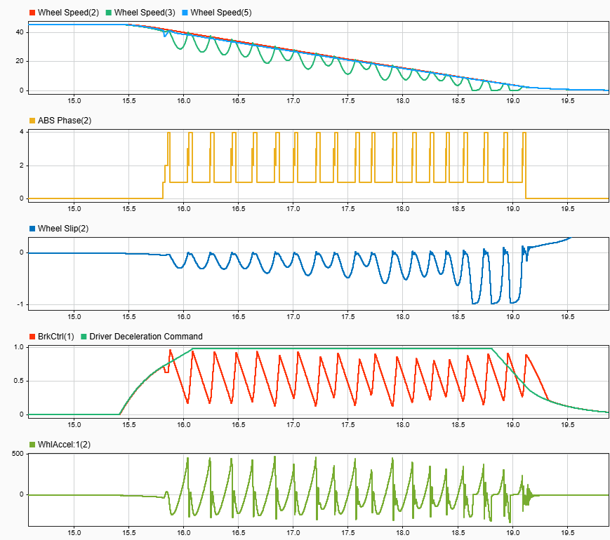
Plots of the Anti-Lock Brake System Block output

The equations use these variables.

AfABS activation flag
ωWheel speed
RWheel loaded radius
vVehicle speed
vtVehicle speed threshold
λWheel slip ratio
aWheel acceleration
iNumber of axles
jNumber of wheels per axle
λijWheel slip ratio of the ith axle with the jth wheel
λtLower slip target threshold
aijWheel acceleration of the ith axle with the jth wheel
at1Lower acceleration target threshold
at2Upper acceleration target threshold
PdDriver deceleration braking command
PdtDriver deceleration braking target threshold
PcBraking commanded by ABS system
PctBrake command target threshold to exit ABS control
N

Number of wheels; the order represented in arrays used in this block is [λ11 λ12 λ21 λ22 ]

The block uses the wheel number, N, to index the input and output signals. This table summarizes the wheel, axle, and corresponding wheel number for a vehicle with:

  • Two axles

  • Two wheels per axle

WheelArray ElementAxle (i)Wheel Number (j)
Front left(1,1)11
Front right(1,2)12
Rear left(1,3)21
Rear right(1,4)22

Examples

Ports

Input

expand all

Normalized brake command from driver, Pd, dimensionless. Array dimensions are 1-by-N.

For example, for a two-axle vehicle with two wheels per axle, signal array dimensions are [1x4].

Range of allowable values: [0,1].

Data Types: double

Wheel slip ratio, λ, dimensionless. Array dimensions are 1-by-N.

For example, for a two-axle vehicle with two wheels per axle, signal array dimensions are [1x4].

Range of allowable values: [–1,1].

Data Types: double

Wheel acceleration, a, in rad/s^2. Array dimensions are 1-by-N.

For example, for a two-axle vehicle with two wheels per axle, signal array dimensions are [1x4].

Range of allowable values: (–inf,inf).

Data Types: double

Vehicle speed, v, in units defined by Input speed unit, SpdUnit.

Data Types: double

Boolean flag, Af, that indicates whether ABS control is permitted to activate. A value of true enables the port. A value of false disables the port.

Data Types: Boolean

Output

expand all

Normalized brake control command, Pc, dimensionless. Vector dimensions are 1-by-N.

For example, for a two-axle vehicle with two wheels per axle, signal vector dimensions are [1x4]. This dimensionless output is converted to an actual brake pressure or torque by a downstream brake actuator model to apply to the individual wheels.

Range of acceptable values: [0,1].

Bus that contains these block calculations.

SignalDescription
WhlSlipWheel slip values
WhlAccWheel acceleration
ABSStatusABS activation status
DecelCmdDeceleration command
BrkCtrlBrake control signal

Parameters

expand all

To edit block parameters interactively, use the Property Inspector. From the Simulink® Toolstrip, on the Simulation tab, in the Prepare gallery, select Property Inspector.

Note

All nonscalar vectorized parameters must have the same length.

Primary Control Parameters

Target braking wheel slip ratio, λ1, dimensionless.

Vector is 1 by the number of wheels, N. If you provide a scalar value, the block uses that value for all wheels.

The target ratio establishes the lower threshold at which ABS becomes active. When the wheel slip ratio drops below this value, provided the vehicle‑speed threshold is satisfied and braking is requested, the ABS control sequence is initiated. The range of acceptable values is [–1, 0].

Programmatic Use

To set the block parameter value programmatically, use the set_param function.

To get the block parameter value programmatically, use the get_param function.

Parameter: TrgtWhlSlip
Values: –0.05 (default) | scalar | vector
Data Types: double

Braking threshold, Pdt, dimensionless.

Vector is 1 by the number of wheels, N. If you provide a scalar value, the block uses that value for all wheels.

This value defines the lower activation threshold for the ABS system. ABS control is exited when deceleration drops below this limit. The range of acceptable values is [0, 1].

Programmatic Use

To set the block parameter value programmatically, use the set_param function.

To get the block parameter value programmatically, use the get_param function.

Parameter: AbsEnBrkThr
Values: 0.1 (default) | scalar | vector
Data Types: double

Vehicle speed threshold, vt, in m/s unless otherwise specified. This value defines the lower activation threshold for the ABS system. When the vehicle speed exceeds this value, provided the wheel slip ratio threshold is satisfied and braking is requested, the ABS control sequence is initiated. The range of acceptable values is [0, inf).

Programmatic Use

To set the block parameter value programmatically, use the set_param function.

To get the block parameter value programmatically, use the get_param function.

Parameter: AbsEnSpdThr
Values: 4 (default) | scalar
Data Types: double

Vehicle input speed unit.

Programmatic Use

To set the block parameter value programmatically, use the set_param function.

To get the block parameter value programmatically, use the get_param function.

Parameter: SpdUnit
Values: m/s (default) | scalar
Data Types: character vector

Advanced Control Parameters

Initial brake command, dimensionless. The range of acceptable values is [0, 1]. A value of zero represents no commanded braking.

Programmatic Use

To set the block parameter value programmatically, use the set_param function.

To get the block parameter value programmatically, use the get_param function.

Parameter: InitBrkCmd
Values: 0 (default) | scalar
Data Types: double

Rate at which the normalized brake command decreases during release, in 1/s.

Vector is 1 by the number of wheels, N. If you provide a scalar value, the block uses that value for all wheels.

The range of acceptable values is (–inf, 0]. Increasing the absolute value of this parameter results in a faster pressure reduction.

Programmatic Use

To set the block parameter value programmatically, use the set_param function.

To get the block parameter value programmatically, use the get_param function.

Parameter: BrkReleaseRate
Values: –10 (default) | scalar | vector
Data Types: double

Rate at which the normalized brake command increases gradually, in 1/s.

Vector is 1 by the number of wheels, N. If you provide a scalar value, the block uses that value for all wheels.

The range of acceptable values is [0, value of BrkRapidIncRate). Increasing the value of this parameter results in a faster pressure reapplication after recovery.

Programmatic Use

To set the block parameter value programmatically, use the set_param function.

To get the block parameter value programmatically, use the get_param function.

Parameter: BrkMildIncRate
Values: 0.2 (default) | scalar | vector
Data Types: double

Rate at which the normalized brake command increases aggressively, in 1/s.

Vector is 1 by the number of wheels, N. If you provide a scalar value, the block uses that value for all wheels.

The range of acceptable values is [0, inf). Increasing the value of this parameter results in a faster return to braking.

Programmatic Use

To set the block parameter value programmatically, use the set_param function.

To get the block parameter value programmatically, use the get_param function.

Parameter: BrkRapidIncRate
Values: 0.5 (default) | scalar | vector
Data Types: double

Lower wheel acceleration threshold for transitions, at1, in rad/s^2.

Vector is 1 by the number of wheels, N. If you provide a scalar value, the block uses that value for all wheels.

The range of acceptable values is [0, inf) and should be smaller than the value of Upper acceleration bound, AccelUpprLmt. Increasing the value of this parameter requires faster wheel recovery before it is considered recovered.

Programmatic Use

To set the block parameter value programmatically, use the set_param function.

To get the block parameter value programmatically, use the get_param function.

Parameter: AccelLowrLmt
Values: 6 (default) | scalar | vector
Data Types: double

Upper wheel acceleration threshold, at2, in rad/s^2.

Vector is 1 by the number of wheels, N. If you provide a scalar value, the block uses that value for all wheels.

The range of acceptable values is [0, inf) and should be larger than the value of Lower acceleration bound, AccelLowrLmt. Increasing the value of this parameter delays transition to the mild increase phase.

Programmatic Use

To set the block parameter value programmatically, use the set_param function.

To get the block parameter value programmatically, use the get_param function.

Parameter: AccelUpprLmt
Values: 303 (default) | scalar | vector
Data Types: double

Exit Logic Parameters

Handoff time, in s. Handoff time is the transition period when ABS control is exited and the brake control output is a blend of the ABS controller output and the driver input. The range of acceptable values is [0, inf).

If Handoff time, HdOffTime is set to zero, no blending occurs, and the control output switches immediately from ABS control to driver deceleration input.

Programmatic Use

To set the block parameter value programmatically, use the set_param function.

To get the block parameter value programmatically, use the get_param function.

Parameter: HdOffTime
Values: 0.2 (default) | scalar
Data Types: double

Brake control threshold, Pct, dimensionless. This value defines the lower reset threshold for the ABS system. ABS control is exited when the normalized brake control drops below this limit. The range of acceptable values is [0, 1].

Programmatic Use

To set the block parameter value programmatically, use the set_param function.

To get the block parameter value programmatically, use the get_param function.

Parameter: BrkCtrlLmt
Values: 0.01 (default) | scalar
Data Types: double

References

[1] Gerard, Mathieu, William Pasillas-Lépine, Edwin De Vries, and Michel Verhaegen. "Improvements to a Five-Phase ABS Algorithm for Experimental Validation." Vehicle System Dynamics 50, no. 10 (October, 2012): 1585–1611.

[2] Reif, Konrad, ed. Brakes, Brake Control and Driver Assistance Systems: Function, Regulation and Components. Springer Gabler, 2014. Bosch Professional Automotive Information.

[3] Reif, Konrad, and Karl-Heinz Dietsche. Automotive Handbook. 10th edition, Revised and Extended, Robert Bosch GmbH, 2018.

[4] Shi, Yue, Bin Li, Jiannan Luo, and Fan Yu. "A Practical Identifier Design of Road Variations for Anti-Lock Brake System." Vehicle System Dynamics 57, no. 3 (March 4, 2019): 336–68.

Extended Capabilities

expand all

C/C++ Code Generation
Generate C and C++ code using Simulink® Coder™.

Version History

Introduced in R2026b