Develop a CAN Replay Model
This example shows how to choose a modeling approach for injecting replayed CAN messages into a model.
Overview
The CAN Replay block allows you to inject CAN data as inputs to a Simulink® model. The data is available in a MAT file, in the form of a variable of struct type with defined fields. For more information, see Log and Replay CAN Messages.
In this example, the file DriveReplay.mat contains a variable canMsgs with logged data that is readily available for use.
load("DriveReplay.mat");
canMsgs
canMsgs = struct with fields:
ID: [1201 1312 512 513 533 561 576 1616 1200 1201 1216 512 513 533 1296 1200 128 133 144 528 529 1201 1312 512 513 533 1200 1201 628 561 576 1296 1200 128 133 144 512 513 528 529 533 1201 1312 1200 1201 512 513 533 1296 … ] (1×100000 uint32)
Extended: [0 0 0 0 0 0 0 0 0 0 0 0 0 0 0 0 0 0 0 0 0 0 0 0 0 0 0 0 0 0 0 0 0 0 0 0 0 0 0 0 0 0 0 0 0 0 0 0 0 0 0 0 0 0 0 0 0 0 0 0 0 0 0 0 0 0 0 0 0 0 0 0 0 0 0 0 0 0 0 0 0 0 0 0 0 0 0 0 0 0 0 0 0 0 0 0 0 0 0 0 0 0 0 0 0 0 0 0 0 … ] (1×100000 uint8)
Remote: [0 0 0 0 0 0 0 0 0 0 0 0 0 0 0 0 0 0 0 0 0 0 0 0 0 0 0 0 0 0 0 0 0 0 0 0 0 0 0 0 0 0 0 0 0 0 0 0 0 0 0 0 0 0 0 0 0 0 0 0 0 0 0 0 0 0 0 0 0 0 0 0 0 0 0 0 0 0 0 0 0 0 0 0 0 0 0 0 0 0 0 0 0 0 0 0 0 0 0 0 0 0 0 0 0 0 0 0 0 … ] (1×100000 uint8)
Error: [0 0 0 0 0 0 0 0 0 0 0 0 0 0 0 0 0 0 0 0 0 0 0 0 0 0 0 0 0 0 0 0 0 0 0 0 0 0 0 0 0 0 0 0 0 0 0 0 0 0 0 0 0 0 0 0 0 0 0 0 0 0 0 0 0 0 0 0 0 0 0 0 0 0 0 0 0 0 0 0 0 0 0 0 0 0 0 0 0 0 0 0 0 0 0 0 0 0 0 0 0 0 0 0 0 0 0 0 0 … ] (1×100000 uint8)
Length: [8 5 8 8 8 8 4 1 8 8 1 8 8 8 3 8 7 8 8 7 8 8 5 8 8 8 8 8 8 8 4 3 8 7 8 8 8 8 7 8 8 8 5 8 8 8 8 8 3 8 7 8 8 7 8 7 8 5 8 8 8 8 4 7 1 8 8 3 8 8 8 8 7 8 8 7 8 8 5 8 8 8 8 8 3 8 4 8 7 8 8 7 8 8 8 8 8 5 3 8 8 8 8 8 8 7 8 8 7 … ] (1×100000 uint8)
Timestamp: [88.6176 88.6178 88.6194 88.6196 88.6199 88.6201 88.6203 88.6204 88.6241 88.6243 88.6244 88.6294 88.6296 88.6299 88.6307 88.6323 88.6325 88.6328 88.6330 88.6333 88.6335 88.6337 88.6339 88.6394 88.6397 88.6399 88.6405 … ] (1×100000 double)
Data: [8×100000 uint8]
It is convenient to set the simulation time step and the initial and final time of the simulation, as follows:
Ts = 0.01;
startTime = round(canMsgs.Timestamp(1)/Ts)*Ts;
stopTime = round(canMsgs.Timestamp(end)/Ts)*Ts;
where the simulation start and stop time are rounded to the nearest integer multiple of the sample time.
Typical Use Cases
The CAN Replay block is useful in the following situations:
Simulation without channels or pacing.
Simulation with transmission of messages over virtual channels.
Simulation with transmission of messages over physical channels.
Simulation Without Channels or Pacing
In this case, the CAN Replay block is used to read the data form the MAT file, and route the CAN messages to its output port. Open the model simulation_without_channels_or_pacing.slx and verify that the configuration of the block is as shown:
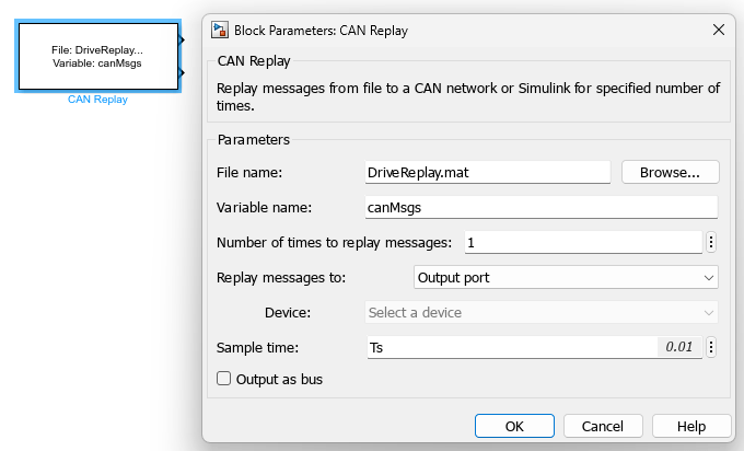
where the Replay messages to is set to Output port. In this case, the Device parameter cannot be set, because no device is used for the transmission.
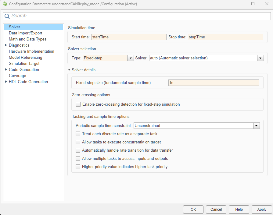
Note the usage of the sample time, Ts, and the decision to replay the messages only once. In order for the simulation to be compatible with these choices, it is necessary to set the Configuration Parameters of the model as follows:
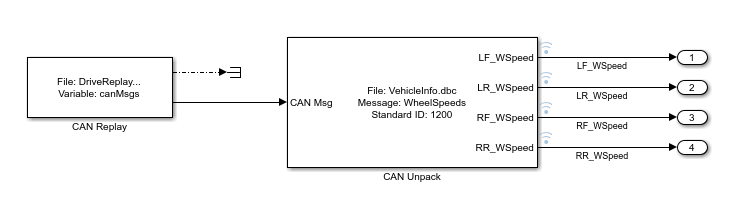
The messages can be decoded via the CAN Unpack block, as in the following diagram. The wheel speed signals can be used as any other Simulink signals in the model, and they are synchronized with the simulation time.
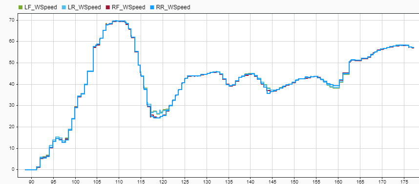
Simulation of the model simulation_without_channels_or_pacing.slx and visualization of the data using the Simulation Data Inspector results in the following:
Simulation with Transmission of Messages over Virtual Channels
Alternatively, it is possible to configure the CAN Replay block to transmit over a virtual channel. The configuration of the block might be as shown:
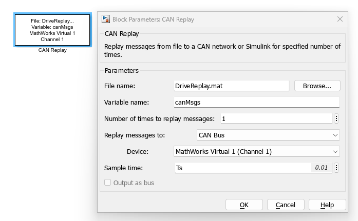
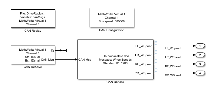
The parameter Replay messages to is set to CAN Bus, and the chosen Device is a MathWorks® virtual channel. Upon applying this configuration, the output ports of the CAN Replay block disappear, because the block is transmitting directly over the selected channel. In addition, the software proposes to insert a CAN Configuration block to configure the device chosen. The CAN Configuration block can be left with its default parameters. An additional block needs to be inserted, namely, a CAN Receive block, configured to received messages from MathWorks Virtual 1 (Channel 1) and to have a sample time equal to Ts. All other parameter values are identical to those in the previous section. The block diagram, available in the model simulation_with_virtual_channels.slx appears as follows:
It is instructive to run a simulation of this model, which leads to the following results:
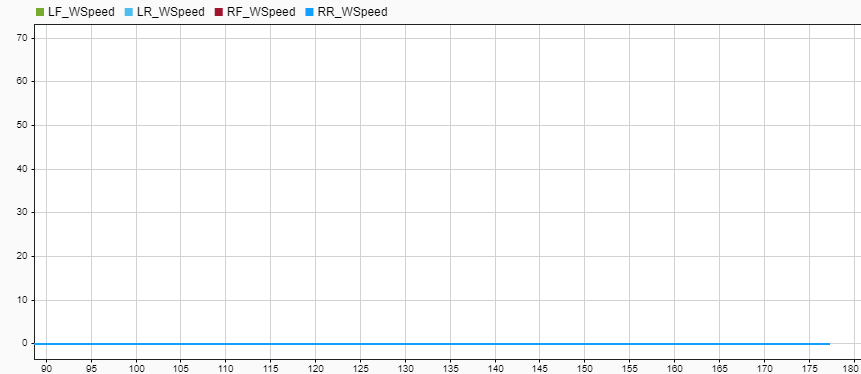
Compared to the previous case, when a device is used, there is no guarantee that the transmission of messages be synchronized with the simulation time. In particular, virtual channels are software buffers that are executed in a different thread, mimicking the behavior of hardware channels but transmitting the data without corruption. In this case, the simulation was completed before the virtual channel started routing the messages to the CAN Unpack block. The resulting signals are therefore zero.
Note that configuring a model to replay CAN messages through virtual channels is not the correct strategy to run a simulation where the data needs to be used in during runtime, because of the delays introduced by those virtual channels. It is, however, the most appropriate and advantageous way to prepare a model to use hardware channels, because switching to use a hardware device requires only modification of block parameters, but no structural modifications of the model (no blocks are added or removed).
One way to mitigate the effect of delays introduced by virtual channels is to use Simulation Pacing Options (Simulink). Upon setting the Simulation time per wall clock second equal to 1, the simulation results for the LF_WSpeed signal are the following:
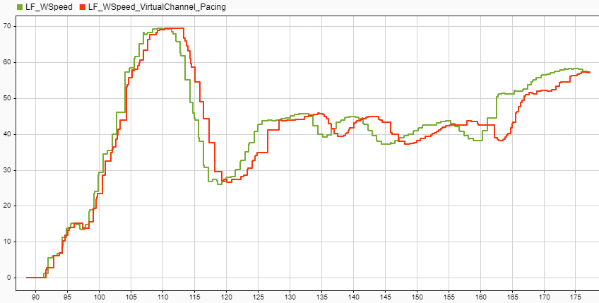
The green signal LF_WSpeed indicates the result obtained without using channels or pacing; the red signal LF_WSpeed_VirtualChannel_Pacing is obtained using virtual channels and simulation pacing. There is an evident delay which is introduced by the virtual channel, which cannot be entirely compensated by the usage of simulation pacing.
Simulation with Transmission of Messages over Physical Channels
When physical channels are used, the desktop computer is connected to the CAN bus via a dedicated hardware device. As far as the timing of the simulation is concerned, the same considerations from the previous section apply. In addition to transmission delays introduced by the channel, hardware devices introduce other real-world effects that virtual channels cannot simulate.
Note that simulation pacing is not a replacement for real-time simulation, which requires dedicated real-time computers and specific transmit/receive blocks. See Get Started with Simulink Real-Time (Simulink Real-Time) for more information.