Coordinate Systems for Display
Several display tools are available for use with the Aerospace Toolbox product. Each tool has a specific coordinate system for rendering motion.
MATLAB Graphics Coordinates
See the Axes Appearance for more information about the MATLAB® Graphics coordinate axes.
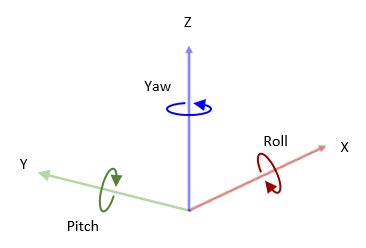
MATLAB Graphics uses this default coordinate axis orientation:
The x-axis points out of the screen.
The y-axis points to the right.
The z-axis points up.
FlightGear Coordinates
FlightGear is an open-source, third-party flight simulator with an interface supported by the blockset.
Flight Simulator Interface Example discusses the toolbox interface to FlightGear.
See the FlightGear documentation at
www.flightgear.orgfor complete information about this flight simulator.
The FlightGear coordinates form a special body-fixed system, rotated from the standard body coordinate system about the y-axis by -180 degrees:
The x-axis is positive toward the back of the vehicle.
The y-axis is positive toward the right of the vehicle.
The z-axis is positive upward, that is, wheels typically have the lowest z values.
AC3D Coordinates
AC3D is a low-cost, widely used, geometry editor available from https://www.inivis.com.
Its body-fixed coordinates are formed by inverting the three standard body coordinate
axes:
The x-axis is positive toward the back of the vehicle.
The y-axis is positive upward, that is, wheels typically have the lowest y values.
The z-axis is positive to the left of the vehicle.
Unreal Engine Coordinates
Unreal Engine® uses a left-handed world-fixed coordinate system with the z-axis positive upward. Positive rotations about the x-axis and y-axis are right-handed, whereas positive rotation about the z-axis is left-handed.
The Aerospace Blockset™ functionality sends Euler angles to Unreal Engine. These angles are applied in the order of rotations being yaw (z-axis), pitch (y), and roll (x-axis).
The coordinate system conversion between Simulink® to Unreal Engine involves conversion from a right-handed to a left-handed system, which, for the NED frame is done by flipping the sign of the z-axis.
Cesium for Unreal Coordinates
Cesium® uses the same world coordinate system as Unreal Engine. When the world origin is aligned with the center of the Earth at the ECEF location, then the y-axis is inverted from the ECEF coordinate system.
In Cesium, when the origin is at the center of the earth
The x-axis is in the plane of the equator, passing through the origin and extending from 180 degrees longitude (negative) to the prime meridian (positive).
The y-axis is also in the plane of the equator, passing through the origin and extending from 90 degrees East longitude (negative) to 90 degrees West longitude (positive). This is inverted from the ECEF y-axis.
The z-axis is in the line between the North and South Poles, with positive values increasing northward.
For more information on ECEF coordinate systems, see ECI and ECEF Coordinates (Aerospace Blockset).
Coordinates Systems for Sensors
When you add sensors on the scenario, you can choose to mount the sensor relative
to the scene origin or the vehicle origin by specifying the Mounting
Location parameter. If you specify the parameter to scene
origin, the sensor remains stationary during the simulation. If you
specify the parameter to a vehicle name, then the sensor is attached to the vehicle.
In addition, you can specify the relative translation and rotation of the sensor
with respect to the scene or vehicle origin by specifying the Relative
translation [X, Y, Z] and Relative rotation [Roll, Pitch,
Yaw] parameters, respectively.
You can choose a coordinate system by specifying the Coordinate system parameter of the sensor. This table illustrates the different coordinate systems you can choose to specify for sensors:
| Coordinate System | Block Parameter Option | Description | |
|---|---|---|---|
| Unreal Editor coordinate system | Default | The Unreal Editor coordinate system is a left-handed Cartesian coordinate system, in m and rad. Axes
Rotation
|
|
| MATLAB coordinate system | MATLAB | The MATLAB coordinate system is a right-handed Cartesian coordinate system with Z-up orientation, in m and rad. Axes
Rotation
|
|
| ISO 8855 standard coordinate system | ISO8855 | The ISO 8855 standard coordinate system is a right-handed Cartesian coordinate system with Z-up orientation, in m and deg. This coordinate system is defined in the ISO 8855 standard. Axes
Rotation
|
|
| X3D ISO standard coordinate system | VRML | The X3D ISO standard coordinate system is a right-handed Cartesian coordinate system with Y-up orientation, in m and rad. Axes
Rotation
|
|
| SAE coordinate system | SAE or AERO | The SAE J670 standard coordinate system is a right-handed Cartesian coordinate system with Z-down orientation, in m and rad. This is defined in the SAE J670 standard. This coordinate system is used for aerospace applications. Axes
Rotation
|
|