AUTOSAR Component Configuration
R2026bAfter you create an AUTOSAR software component model configured for the AUTOSAR Classic Platform in Simulink®, use the Code Mappings Editor and the AUTOSAR Dictionary to further develop the AUTOSAR component. The Code Mappings Editor and the AUTOSAR Dictionary provide mapping and properties views of the component model, which can be used separately and together to configure the AUTOSAR component in these ways.
Code Mappings Editor — Using a spreadsheet format, displays entry-point functions, inports, outports, and other Simulink elements relevant to your AUTOSAR software component model. Use this view to map model elements to AUTOSAR component elements from a Simulink model perspective.
AUTOSAR Dictionary — Using a tree format, displays a mapped AUTOSAR component and its elements, communication interfaces, computation methods, software address methods, and XML options. Use this view to configure AUTOSAR elements from an AUTOSAR component perspective.
Alternatively, you can configure AUTOSAR mapping and properties programmatically. See Configure and Map AUTOSAR Component Programmatically.
In a model for which AUTOSAR system target file autosar.tlc
is selected, create or open a mapped view of the AUTOSAR model. In the model window, do
one of the following:
From the Apps tab, open the AUTOSAR Component Designer app.
Click the perspective control in the lower-right corner and select Code.
If the model has not yet been mapped to an AUTOSAR software component, the AUTOSAR Component Quick Start opens. To configure the model for AUTOSAR component development, work through the quick-start procedure and click Finish. For more information, see Create Mapped AUTOSAR Component with Quick Start.
The model opens in the AUTOSAR Code perspective. This perspective displays the model and directly below the model, the Code Mappings Editor. This is the perspective for models configured for the AUTOSAR Classic Platform. You can view this model by entering this command in your MATLAB® Command Window:
openExample("autosar_swc_slfcns");
The Code Mappings Editor provides in-canvas access to AUTOSAR mapping
information, with batch editing, element filtering, easy navigation to model elements
and AUTOSAR properties, and model element traceability. To view and modify additional
AUTOSAR attributes for an element, select the element and click the  icon.
icon.
To open an AUTOSAR properties view of the component model, either click the
AUTOSAR Dictionary button  in the Code Mappings Editor or, on the
AUTOSAR tab, select Code Interface > AUTOSAR Dictionary. The AUTOSAR Dictionary opens.
in the Code Mappings Editor or, on the
AUTOSAR tab, select Code Interface > AUTOSAR Dictionary. The AUTOSAR Dictionary opens.
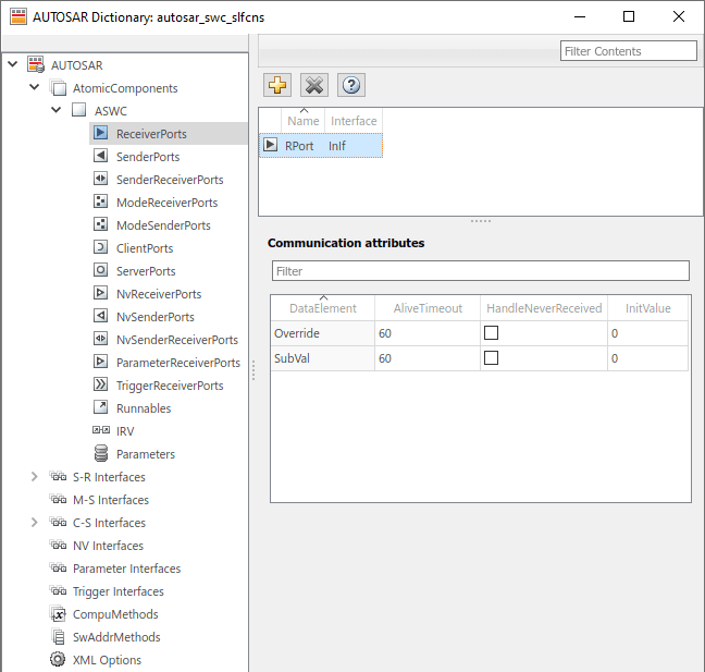
As you progressively configure the model representation of the AUTOSAR component, you can:
Switch between the Simulink modeling perspective and AUTOSAR code perspective, by selecting AUTOSAR tab menu entries or by clicking buttons.
Use the Filter contents field (where available) to selectively display some elements, while omitting others, in the current view.
In the Code Mappings Editor, click the Update button
 to update the Simulink to AUTOSAR mapping of the model with changes to Simulink entry-point functions, data transfers, and function
callers.
to update the Simulink to AUTOSAR mapping of the model with changes to Simulink entry-point functions, data transfers, and function
callers.In the Code Mappings Editor, click the Validate button
 to validate the AUTOSAR component
configuration.
to validate the AUTOSAR component
configuration.In the Code Mappings Editor, with an element selected, click the Edit icon
to view and modify additional AUTOSAR
attributes for the element.

