MSK Signal Recovery in Simulink
This example shows how to observe and adjust channel impairments for MSK signal recovery by using a Simulink® model.
In this example, you use the doc_commmsksync model to apply timing phase, carrier phase, and carrier frequency offsets to a signal modulated with minimum shift keying (MSK). Using the control switches and signal displays, you can observe the simulation results and then change settings to improve signal recovery.
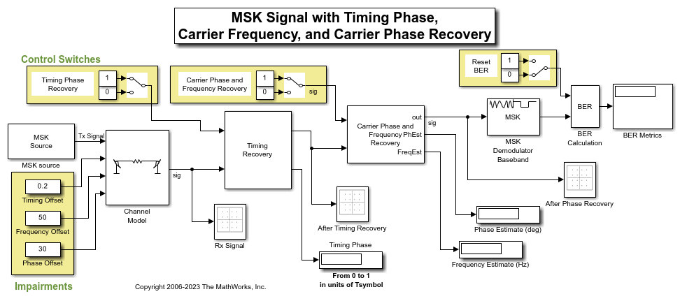
The doc_commmsksync model transmits the MSK-modulated signal filtered through an impaired channel. The model includes these subsystem and block components:
MSK Source subsystem — An MSK Modulator Baseband block modulates equiprobable symbols received from a Bernoulli Binary Generator block.
Channel Model subsystem — The channel model incorporates independently variable offsets in the timing phase, frequency, and phase. The channel model also includes the AWGN Channel block
Timing Recovery subsystem — Signal timing recovery uses an MSK-Type Signal Timing Recovery block.
Carrier Synchronizer block
MSK Demodulator Baseband block
Block to compute and display bit error rate (BER) results
While loading, the model initializes parameters that several blocks share.
When you run the simulation, the displays show impairment value estimates and BER metrics. The displayed phase offset estimate may fluctuate rapidly because the Carrier Synchronizer block performs both frequency and phase correction. The BER Metrics display shows a three-element vector containing the calculated BER, the number of errors observed, and the number of bits processed.
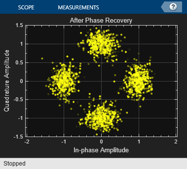
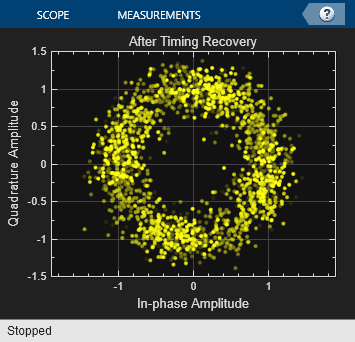
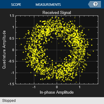
Separate Constellation Diagram blocks show the signal as received, after timing recovery, and after phase recovery. The constellations provide a compelling visual rendition of the recovery algorithms in action. To immediately show the effects on the scatter plots, while the simulation is running, toggle the Control Switches for the recovery scheme algorithms or adjust values in the Impairments section independently. To calculate the steady-state BER, use the Reset BER switch to restart the BER computation after the signal has reached a steady state.
To learn more, investigate further:
Set the frequency offset to 0, and then observe the displayed signal constellations and estimated phase offset.
Observe that the Carrier Synchronizer block is set for a QPSK constellation with a phase offset of 0 degrees for the input MSK signal.
Vary the error update gain of the MSK-Type Signal Timing Recovery block to assess its ability to track constant and time-varying offsets. To access the block, open the Timing Recovery subsystem and then open the Timing Recovery Algorithm subsystem.