Orthogonal Frequency Division Multiplexing Modulation
Orthogonal frequency division multiplexing (OFDM) modulation is a linear baseband modulation technique of encoding digital data on multiple carrier frequencies. The transmitter uses an inverse fast Fourier transform (IFFT) to combine (modulate) multiple closely spaced orthogonal subcarrier signals with overlapping spectra to carry data in parallel. The receiver uses an FFT to demodulate the signal.
Communications Toolbox™ software includes these modulation and demodulation functions, System objects, and blocks to model OFDM modulation.
| Functions | System objects | Blocks |
|---|---|---|
OFDM
As described in Proakis ([2]), in an OFDM system with N subchannels, the symbol rate 1/T is reduced by a factor of N relative to the symbol rate on a single-carrier system that employs the entire bandwidth, W, and transmits data at the same rate as OFDM. Hence, the symbol interval in the OFDM system is T = NTs , where Ts is the symbol interval in the single-carrier system. By selecting N to be sufficiently large, the symbol interval T can be made significantly larger than the time duration of the channel-time dispersion. Thus, intersymbol interference can be made arbitrarily small through the selection of N. In other words, each subchannel appears to have a fixed frequency response C(fk), k = 0, 1, . . . , N - 1.
OFDM Modulation Examples
These examples demonstrate OFDM modulation techniques.
Apply OFDM with User-Specified Pilot Indices
Construct an orthogonal frequency division multiplexing (OFDM) modulator and demodulator pair and specify their pilot indices. The OFDM modulator System object™ enables you to specify pilot subcarrier indices consistent with the constraints described by the info object function. In this example, for OFDM transmission over a 3x2 channel, pilot indices are created for each of the three transmit antennas. Additionally, the pilot indices differ between odd and even symbols.
Create an OFDM modulator object having five symbols, three transmit antennas, and length six windowing.
ofdmMod = comm.OFDMModulator( ...
    FFTLength=256, ...
    NumGuardBandCarriers=[12; 11], ...
    NumSymbols=5, ...
    NumTransmitAntennas=3, ...
    PilotInputPort=true, ...
    Windowing=true, ...
    WindowLength=6);
Specify pilot indices for even and odd symbols for the first transmit antenna.
pilotIndOdd = [20; 58; 96; 145; 182; 210];
pilotIndEven = [35; 73; 111; 159; 197; 225];

pilotIndicesAnt1 = cat(2,pilotIndOdd,pilotIndEven,pilotIndOdd, ...
    pilotIndEven,pilotIndOdd);
Generate pilot indices for the second and third antennas based on the indices specified for the first antenna. Concatenate the indices for the three antennas and assign them to the PilotCarrierIndices property.
pilotIndicesAnt2 = pilotIndicesAnt1 + 5;
pilotIndicesAnt3 = pilotIndicesAnt1 - 5;

ofdmMod.PilotCarrierIndices = ...
    cat(3,pilotIndicesAnt1,pilotIndicesAnt2,pilotIndicesAnt3);
Create an OFDM demodulator with two receive antennas based on the existing OFDM modulator System object. Determine the data and pilot dimensions using the info function.
ofdmDemod = comm.OFDMDemodulator(ofdmMod);
ofdmDemod.NumReceiveAntennas = 2;

dims = info(ofdmMod)
dims = struct with fields:
     DataInputSize: [215 5 3]
    PilotInputSize: [6 5 3]
        OutputSize: [1360 3]
Generate data and pilot symbols for the OFDM modulator given the array sizes specified in modDim.
dataIn = ...
    complex(randn(dims.DataInputSize), ...
    randn(dims.DataInputSize));
pilotIn = ...
    complex(randn(dims.PilotInputSize), ...
    randn(dims.PilotInputSize));
Apply OFDM modulation to the data and pilots.
modOut = ofdmMod(dataIn,pilotIn);
Pass the modulated data through a 3x2 random channel.
chanGain = complex(randn(3,2),randn(3,2));
chanOut = modOut * chanGain;
Demodulate the received data using the OFDM demodulator object.
[dataOut,pilotOut] = ofdmDemod(chanOut);
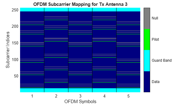
Show the resource mapping for the three transmit antennas. The gray lines in the figure show the placement of custom nulls to avoid interference among antennas.
showResourceMapping(ofdmMod)


For the first transmit and first receive antenna pair, demonstrate that the input pilot signal matches the input pilot signal.
pilotCompare = ...
    abs(pilotIn(:,:,1)*chanGain(1,1)) - abs(pilotOut(:,:,1,1));
max(pilotCompare(:) < 1e-10)
ans = logical
1
Apply OFDM to QPSK Signal Spatially Multiplexed over Two Streams
Apply OFDM modulation to a QPSK signal that is spatially multiplexed over two transmit streams.
Initialize input parameters and generate random data for each stream.
M = 4; % Modulation order for QPSK
nfft = 64;
cplen = 16;
nSym = 5;
nStreams = 2;
nullIdx = [1:6 33 64-4:64]';
pilotIdx = [12 26 40 54]';
numDataCarrs = nfft-length(nullIdx)-length(pilotIdx);
pilots = repmat(pskmod((0:M-1).',M),1,nSym,nStreams);

stream1 = randi([0 M-1],numDataCarrs,nSym);
stream2 = randi([0 M-1],numDataCarrs,nSym);
QPSK modulate data individually for each stream. Perform OFDM modulation.
qpskSig(:,:,1) = pskmod(stream1,M);
qpskSig(:,:,2) = pskmod(stream2,M);
y1 = ofdmmod(qpskSig,nfft,cplen,nullIdx,pilotIdx,pilots);
References
[1] IEEE® Standard 802.16-2017. "Part 16: Air Interface for Broadband Wireless Access Systems." March 2018.
[2] Proakis, John G. Digital Communications. 5th ed. New York: McGraw Hill, 2007.
See Also
Functions
Objects
comm.RaisedCosineTransmitFilter|comm.RaisedCosineReceiveFilter|comm.OFDMModulator|comm.OFDMDemodulator
Blocks
- Raised Cosine Transmit Filter | Raised Cosine Receive Filter | OFDM Modulator Baseband | OFDM Demodulator Baseband