Programmable FIR Filter for FPGA
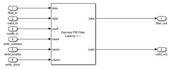
This example shows how to implement a programmable FIR filter for hardware. You can program the filter to the required response by loading the coefficients into internal registers using a memory-style interface.
This example implements a bank of two filters, each with a different response. Both filters have the same length and symmetry of coefficients. This pattern of coefficients allows the block to share multipliers for symmetric coefficients in the same way for both filters. The same filter hardware can be programmed with new coefficients to obtain a different filter response.
Model Programmable FIR Filter
This example implements two FIR filters, one with a lowpass response and the other with a highpass response. The coefficients are specified in the Model Properties>Callbacks>InitFcn function.

The Programmable FIR(Memory Interface) subsystem contains the Discrete FIR Filter block, with the Coefficients source parameter set to Input port (Memory interface). This configuration enables a memory-style set of ports where you can write the coefficients into the filter. First, the Host Behavioral Model subsystem loads the lowpass coefficients to the FIR filter. The model delays the input chirp samples until the first coefficient write is complete. Then the Host Behavioral Model subsystem loads the highpass coefficients.
While you write coefficients to the filter, the filter ignores any input data samples. This model stops sending input data while the coefficients are changing. You can also use the output valid signal to determine when the output data is valid.

The Discrete FIR Filter block in this model is configured to use a fully parallel direct form systolic architecture. The block also supports using the memory-style programmable coefficients when the block uses the parallel transposed or serial architectures. The Coefficient prototype parameter is set to one of the coefficient vectors. This setting enables the block to optimize hardware resources based on the symmetry and position of zero-valued coefficients. When you specify a prototype, all input coefficient sets must match the prototype in symmetry and location of zero-valued coefficients. For more detail about how to use the prototype to optimize filter resources, see Optimize Programmable FIR Filter Resources (DSP HDL Toolbox).
Simulink Simulation Results
To view the input and output data and the signals of the coefficient interface, open the Scope and run the example model.

Using the Logic Analyzer
You can also view the signals from the model in the Logic Analyzer. The Logic Analyzer enables you to view multiple signals in one window and lets you find the transitions in the signals and measure the latency between signals.
Launch the Logic Analyzer from the model's toolstrip.

The model already has some signals of interest (input coefficients, write address, write enable, write done, filter in, filter out, and valid signals) added to the Logic Analyzer for observation.

The Logic Analyzer display can also be controlled on a per-wave or per-divider basis. To modify an individual wave or divider, select a wave or divider and then click the Waves tab. A useful mode of visualization in the Logic Analyzer is the Analog format.

For more information, see Logic Analyzer.
Generate HDL Code and Test Bench
You must have an HDL Coder™ license to generate HDL code for this example model. Use this command to generate HDL code.
systemname = [modelname '/Programmable FIR(Memory Interface)'];
makehdl(systemname);
Use this command to generate a test bench that compares the results of an HDL simulation against the Simulink simulation behavior.
makehdltb(systemname);
See Also
Logic Analyzer | Discrete FIR Filter (DSP HDL Toolbox)
Topics
- Optimize Programmable FIR Filter Resources (DSP HDL Toolbox)