Model-Based BLDC Motor Control on Renesas RH850 U2A Microcontroller Using Simulink
This example shows how to use the Embedded Coder Support Package for Renesas RH850 Microcontrollers to implement and deploy sensorless Brushless DC (BLDC) motor control on a Renesas RH850 Microcontroller using model-based design in Simulink. You will simulate, generate code, and run both open-loop and closed-loop control strategies, leveraging the Renesas Motor Control Kit.
Prerequisites
Before you begin,
Complete Simulink Onramp tutorial.
Complete the Hardware Setup for Embedded Coder Support Package for Renesas RH850 Microcontrollers.
If you obtain the motor parameters from the datasheet or other sources, update the motor parameters and Inverter parameters in the model initialization script associated with the Simulink® models. For instructions, see Estimate Control Gains and Tune Control Parameters (Motor Control Blockset).
Required Hardware
Renesas RH850 based Inverter for motor control.
DC Power Supply (> 20V)
E2 emulator
BLDC motor
FTDI connector (optional)
Hardware Connections
Perform these steps to connect and configure your hardware before running the example.
1. Connect the E2 Emulator.
Connect the E2 Emulator to header X1 on the U2A Inverter board.
Align the 1 on the emulator with the 1 marked on the board.

2. Connect DC Power Supply.
Connect the power supply outputs to Bat+ and Bat- terminals on the Inverter board.
Use a DC power supply rated for at least 20V.

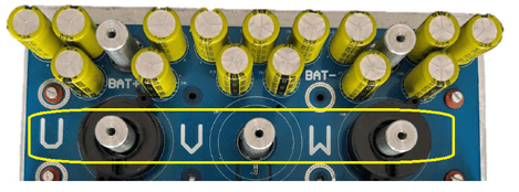
3. Connect the Motor.
Connect the three motor phases to the U, V, and W terminals on the Inverter board.
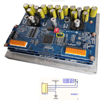
4. (Optional) Connect FTDI for UART Communication.
If UART communication is needed, connect an FTDI USB-to-UART adapter to the J1 4-pin UART header.
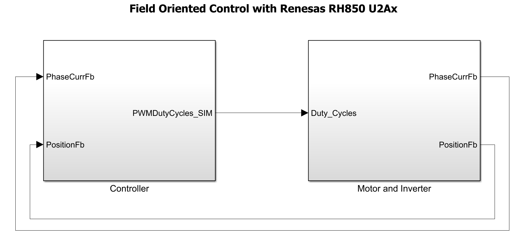
System Overview
The system uses two main control loops, current control and speed control loops, which work together to achieve precise and efficient motor operation from startup through steady-state running.
Start MATLAB and Top-Level Simulink Model
The example includes a top-level model that you can use for system-level simulation and two referenced models for current control and speed control.
Start MATLAB and open the MotorControlRH850Example.slx Simulink model.
modelName = "MotorControlRH850Example";
open_system(modelName)
The top model MotorControlRH850Example opens. The top-level model in this example comprises of two subsystems CurrentControl and SpeedControl.
To view the current control model, navigate to MotorControlRH850Example > Controller > CurrentControl model.

To view the speed control model, navigate to MotorControlRH850Example > Controller > SpeedControl model.

Configure Top Model
In the MotorControlExample model, press Ctrl+E or navigate to Modeling > Model Settings to open the Configuration Parameters dialog box.
In the Hardware Implementation pane, set Hardware board to
Renesas RH850 U2A Based, Device Series toU2A, and Processing Unit toU2A16.Click Apply and OK.
V/F Controller
Used to check the integrity of the setup in open loop.
Does not use any current or position feedback.
Applied voltage is calculated in proportion to the requested speed (frequency).
In the model, the requested frequency is set to 720 RPM.
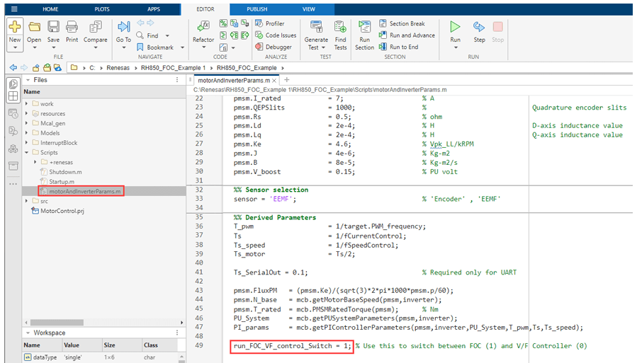
To run the motor in V/F control, set the value of run_FOC_VF_control_switch to 0 in the motorAndInverterParams.m file.

Setting the run_FOC_VF_control_switch parameter, runs the motor in V/F Control.

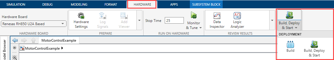
Click Build, Deploy & Start on the Hardware tab to deploy the Simulink model to the hardware.
Closed-Loop Speed Control
Current-Controlled Startup:
Position is generated by software based on the required speed.
A PI controller is used for current control.
Closed Loop Speed Control:
Position is obtained from an observer (Extended EMF Observer).
A speed PI controller is used.
This control loop runs at a slower rate (2 kHz)
Current Control Loop
Runs at 20 kHz using the ADC interrupt for real-time responsiveness.
The ADC samples phase currents (Ia, Ic), which are offset-compensated for accuracy.
Supports both open-loop and closed-loop operation:
Open-loop: Used during startup to safely spin the motor and validate PWM generation before switching to closed-loop.
Closed-loop: Compensated currents are fed to a controller that computes voltage/current references for optimal performance. An output scaling block selects between open- and closed loop commands to generate PWM duty cycles.
Position and Speed Estimation
An Extended EMF Observer estimates rotor position (Theta) and speed from measured voltages/ currents, enabling sensorless operation—even at startup or low speeds.
Estimated position is used for both control modes; speed feedback is used in the speed control loop.
Speed Control Loop
Runs at 1 ms intervals to regulate motor speed.
Implements a discrete PI controller with anti-windup and reset, generating current reference for the current control loop.
Transitions between open- and closed-loop modes are managed by a controller block.
Switching Between Open and Closed-Loop Control
In this example, the motor control system automatically transitions from open-loop to closed-loop control within the controller block.
OpenLoop State: The system begins in open-loop state, using a fixed speed reference to reliably start the motor.
ClosedLoopTemp State: Once the motor reaches a predefined speed threshold, the controller briefly enters an intermediate state to stabilize operation and then switches to closed-loop mode.
ClosedLoop State: In closed-loop mode, real-time speed feedback is used for precise speed regulation.
No manual intervention is required. The transition between open- and closed-loop control is managed automatically by the controller block based on the configured speed threshold.
Simulate Model
1. Open the MotorControlExample model.
2. In the motorAndInverterParams.m file, set the value of run_FOC_VF_control_switch to 1.
3. Click Run on the Simulation tab to simulate the model.
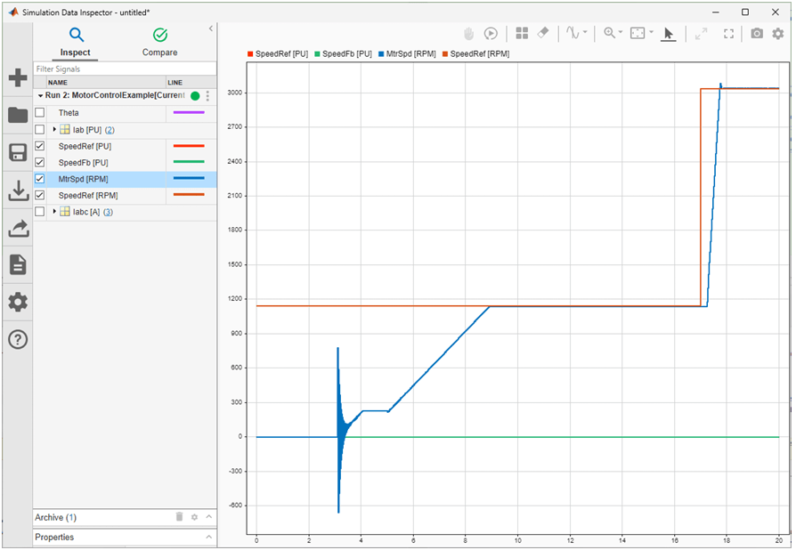
4. Click Data Inspector on the Simulation tab. The desired signal of interest can be logged and viewed in Simulink data inspector.
Generate Code, Deploy, and Run Model on Target Hardware
When you switch Simulink to build and deploy mode, the model automatically generates embedded code tailored for your Renesas hardware. This is achieved using driver blocks within the model, which abstract all low-level interactions with the Microcontroller. Once generated, the code is deployed directly to the target hardware.
Complete the following steps to generate code and run the FOC algorithm on the target hardware.
1. Open the MotorControlExample model.
2. Click Build, Deploy & Start on the Hardware tab to deploy the target model to the hardware.
3. Follow the build process by opening the diagnostic viewer using the link provided at the bottom of the model canvas. You can observe the code generation report that contains code for model traceability. The code is deployed on to the Renesas hardware.
Deploying to Renesas RH850 based Inverter
Due to an issue with the Inverter board, deploying Simulink generated code directly to the board is not possible. Instead, use the below workaround to run the Simulink generated code on hardware.
1.Download CS+ from the Renesas website using the following link:
2. Install CS+ by running the downloaded installer and following the on-screen instructions.
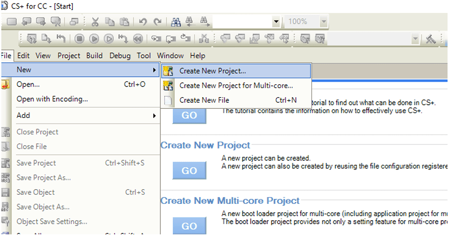
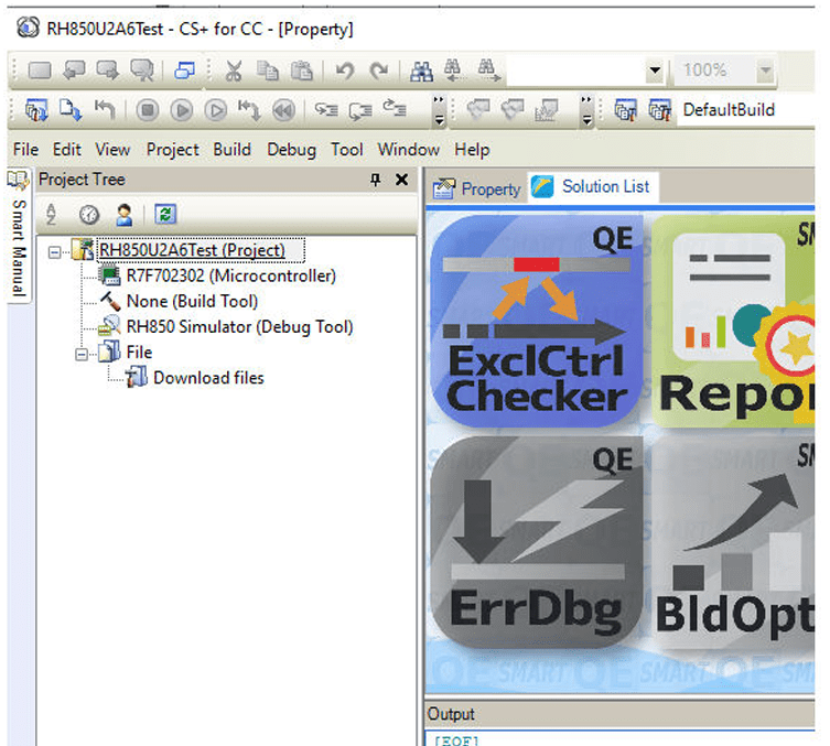
3. Start CS+ and create a new debug project as shown below.
4. Select the target device and then from the Kind of project drop-down list select Debug only.
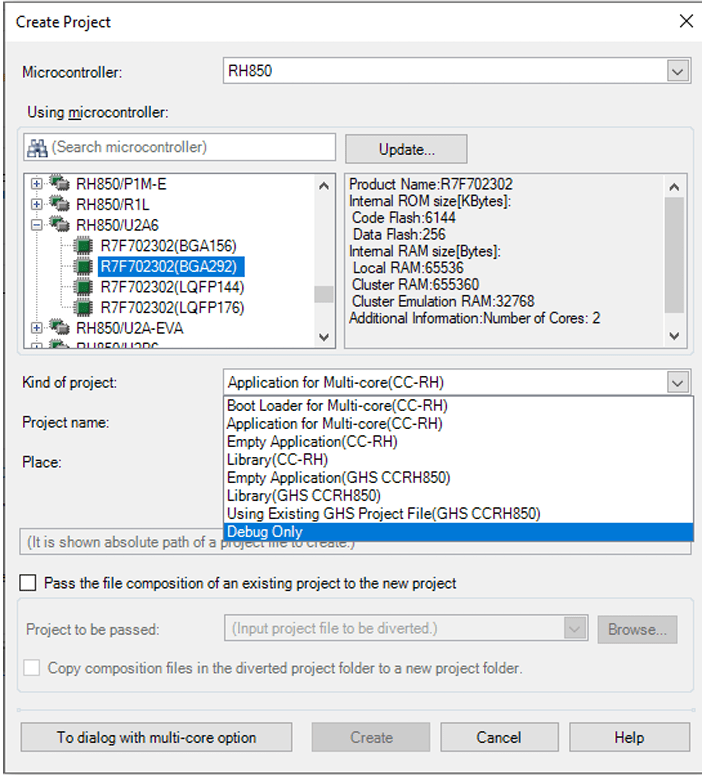
5. Enter a name for the project and select the folder for the project.
Once the project is created, it will appear as shown below.
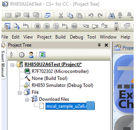
6. Locate the folder containing .abs file generated by Simulink, then drag it into the CS+ workspace under Download files. The file will appear in the list as shown below.
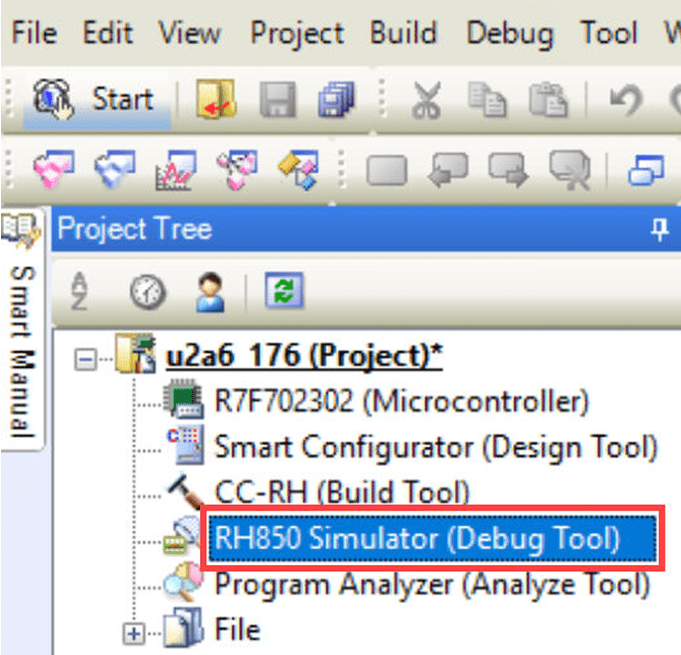
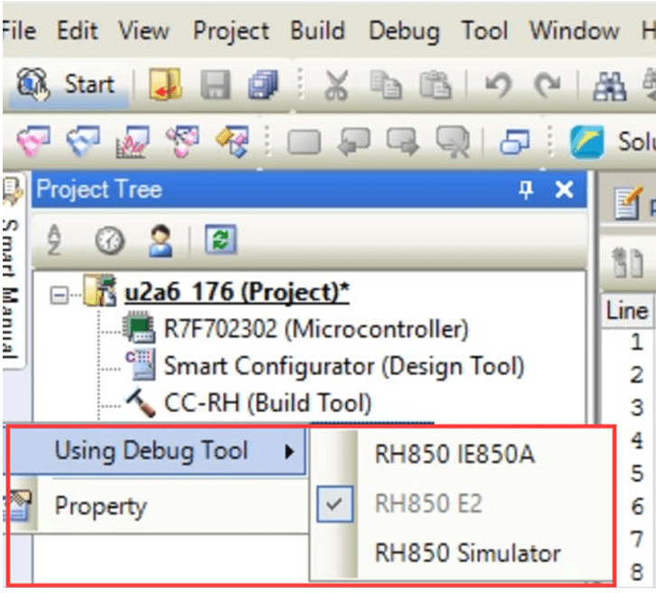
7. In the project tree, right-click RH850 Simulator (Debug Tool) and from the Using Debug Tool option, select RH850 E2.
8. Click on the Download icon to deploy and start debugging the code on the hardware.
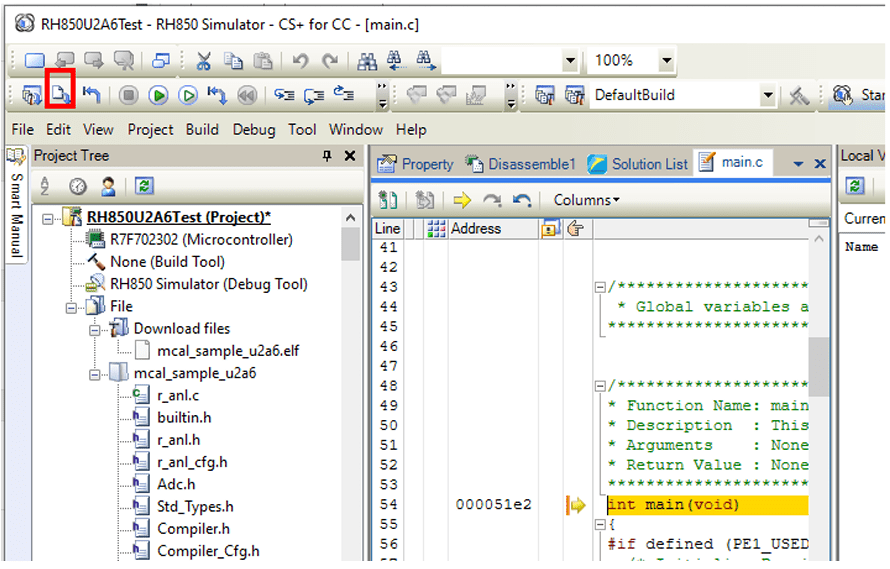
9. Click on the Run icon to start running the code on the hardware.

Connecting an External Inverter Board
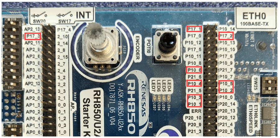
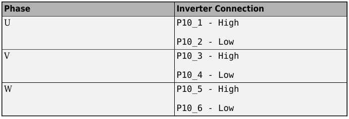
1. Connect PWM pins to the Inverter
Locate the PWM pins, P10_1 to P10_6 and connect them to the Inverter.
2. Connect Analog Signals.
Locate the analog pins:
P17_1 (Ia), P17_2 (Ib), andP17_3 (Ic)and connect them for analog input/output.
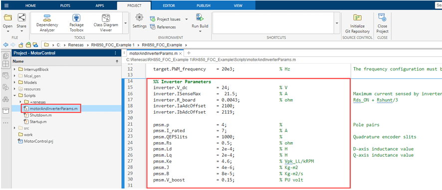
3. Update Motor and Inverter board parameters In the motorAndInverterParams.m file, update the motor and Inverter parameters as per your motor and Inverter board.
4. Click Build, Deploy & Start on the Hardware tab to deploy the target model to the hardware.