Configure Generated Code According to Interface Control Document Specifications
This example shows how to configure code generation settings for a model according to specifications in an interface control document (ICD). The example also shows how to store shared Simulink® variables and data objects in a data dictionary.
An ICD describes the data interface between software components. To exchange and share data, the components declare and define global variables that store signal and parameter values according to the ICD. The ICD names the variables and lists characteristics such as data type, physical units, and parameter values. When you create component models in Simulink, you can configure the models such that the generated code conforms to the ICD. For example, you can use the ICD as a reference source while configuring models interactively or you can automate configuration by using a script to import data from an ICD.
The example assumes that you use the original example files. If you choose to make a local copy of the files and rename the example model, you must change the setting of the Owner property of model data elements to match the new model name as described in the instructions.
Explore Interface Control Document
In Microsoft® Excel® or another compatible program, open the ex_ICD_PCG.xlsx workbook and review the contents of the worksheets.
open ex_ICD_PCG.xlsxSignalsworksheet. Each row represents a signal that crosses the interface boundary. Inspect the cell values in the worksheet. TheOwnercolumn identifies the name of the component that allocates memory for a signal. TheDataTypecolumn names the signal data type in memory. For example, the worksheet uses the expressionBus: EngSensorsto name the structure typeEngSensors.Parametersworksheet. TheValuecolumn lists the value of each parameter. If the value of a parameter is nonscalar, the value is stored in its own separate worksheet, which has the same name as the parameter.Numeric Typesworksheet. Each row represents a named numeric data type. In this ICD, the data uses single-precision floating-point data. TheIsAliascolumn indicates whether the C code uses the name of the data type (for example,s16En3) or uses the name of the primitive integer data type that corresponds to the word length (such asshort). TheDataScopecolumn indicates whether the generated code exports or imports the data type definition.Structure Typesworksheet. Each row represents a structure type or a field of a structure type. For structure types, the value in theDataTypecolumn isstruct. Subsequent rows that do not usestructrepresent fields of the preceding structure type. This ICD defines structure type,EngSensors, with four fields:throttle,speed,ego, andmap.Enumerated Typesworksheet. Similar to theStructure Typesworksheet, each row represents an enumerated type or an enumeration member. This ICD defines enumerated typesld_FuelModes.
Explore External Code
Some data items in the ICD belong to other_component, which is a component that exists outside of MATLAB®. Open and explore the content of these example files, which define and declare the external data:
edit ex_inter_types.h
edit ex_inter_sigs.c
edit ex_inter_sigs.h
Explore Example Model
In this example, you generate code from the controller model ConfigCodeGenBasedOnICD. Open the model.
open_system('ConfigCodeGenBasedOnICD');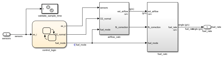
Some signals in the controller model have names, for example, the input signal sensors. Some block parameters in the model refer to Simulink.Parameter objects in a data dictionary. For example, in the airflow_calc subsystem, the Pumping Constant block uses the parameter objects PumpCon, SpeedVect, and PressVect. These parameter objects set the values of the corresponding block parameters. You can apply code generation settings to the signals and parameter objects.
The controller model is linked to data dictionary ConfigCodeGenBasedOnICD.sldd. Explore the data dictionary.
In the lower-left corner of the controller model, click the model data badge.
Click the External Data link.
In the Model Explorer Model Hierarchy pane, expand the nodes ConfigCodeGenBasedOnICD, External data, and ConfigCodeGenBasedOnICD.
Select Design Data.
The dictionary stores:
Parameter objects
Simulink.NumericTypeobjects, such asu8En7Simulink.Busobject,EngSensors
Configure Model Design Data According to ICD
Open the ICD spreadsheet
ex_ICD_PCG.xlsx, if not open already.In the Simulink Editor window for the controller model, navigate to the root level of the model.
On the Modeling tab, click Model Data Editor.
In the Model Data Editor, click the Change scope button. The Model Data Editor shows information about data items in the model subsystems.
Click the Show/refresh additional information button. The Model Data Editor shows information about data objects (the
Simulink.Parameterobjects in the data dictionary) that the model uses.
Configure Design Settings for Signals
In the ICD, click the Signals tab.
In the Model Data Editor, click the Inports/Outports tab.
Make sure that the configuration settings for Inport block
sensorsmatch the ICD specification. Data Type must be set to Bus: EngSensors.Make sure that the configuration settings for Outport block
fuel_ratematch the ICD specification. Data Type must be set tos16En7. Min must be set to0.8000.1.7000.g/s.Make sure that the configuration settings for signal
fuel_modematch the ICD specification. Becausefuel_modeis an output signal of a Stateflow chart, you must use Model Explorer to configure the design settings. In the model, navigate into the Stateflow chart. Open Model Explorer. In the Model Explorer Contents pane (the middle pane), selectfuel_mode. Click the verical dots next to the signal name, hover overfuel_mode(ConfigCodeGenBasedOnICD.sldd)and select Open. In the Simulink.signal: fuel_mode dialog box, on the Design tab, Data Type must be set toEnum:sld_FuelModes.
Configure Design Settings for Parameters
In the ICD, click the Parameters tab.
Navigate to the root level of the control model.
In the Model Data Editor, click the Parameters tab. Then, click the Scope button.
Use the Filter contents box to search for parameter
PressEst. The Model Data Editor shows two rows: one row that corresponds to parameter objectPressEstand one row that corresponds to the block parameter that usesPressEst.Make sure that the configuration settings for parameter
PressEstmatch the ICD specification. Data Type must beu8En7. Value must be a 19x45 matrix of numeric values.Make sure that the Data Type and Value settings for parameters
PumpCon,SpeedEst,ThrotEst, andRampRateKizmatch the ICD specification.
Configure Design Settings for Numeric Types
In the ICD, click the Numeric Types tab.
If the Model Explorer is not open, open it.
In the Model Hierarchy pane, navigate to the design data in the data dictionary for the controller model (ConfigCodeGenBasedOnICD> External Data>ConfigCodeGenBasedOnICD>Design Data).
In the Contents (middle) pane, select the
Simulink.NumericTypeobjectu8En7. This object represents one of thetypedefstatements inex_inter_types.h.In the right pane, on the Design tab, confirm that the setting for Data type mode aligns with the ICD specification.
Make sure that the design configuration for numeric types
s16En3,s16En7, ands16En15matches the ICD specification.
Configure Design Settings for Structures
In the ICD, click the Structure Types tab.
In the Model Explorer Contents pane, select
EngSensors. ThisSimulink.Busobject represents the structure type defined inex_inter_types.h.Confirm that the data type configuration aligns with the ICD specification. In the right pane, on the Design tab, or in the Type Editor, adjust the bus signal configurations (for example, settings for Min and Max) to align with the ICD specification.
Configure Design Settings for Enumerated Types
In the ICD, click the Enumerated Types tab.
Open the file
sld_FuelModes.m, which defines the class for the enumerated typesld_FuelModes.Confirm that the class definition aligns with the ICD specification. In the file sld_FuelModes.m, adjust member names and underlying integer values to align with the ICD specification.
Configure Model for Code Generation According to ICD
Open the ICD, if not open already.
Open the Embedded Coder app.
Configure Code Generation Settings for Inport and Outport Blocks
In the ICD, click the Signals tab. The Owner column in the ICD implies that a different component (
other_component), noConfigCodeGenBasedOnICD, provides the code definition of thesensorsvariable.Include the C source code file that defines the variable
sensors. In the Simulink Editor, on the C Code tab, select Settings> C/C++ Code generation settings. Make sure that the code generation custom code parameter Source files is set toex_inter_sigs.c.In the Simulink Editor, on the C Code tab, select Code Interface> Individual Element Code Mappings.
In the Code Mappings editor, click the Inports tab.
Select the row for
sensors. Because the source code definition is provided in the external fileex_inter_sigs.c, which you configured in step 2, Storage class must be set toImportFromFile.Click the
 icon. Check that the HeaderFile property setting matches the ICD specification,
 ex_inter_sigs.h. Make sure that a value is specified for the Identifier property. This property specifies the variable name for the data element in the generated code.In the Code Mappings editor, click the Outports tab.
Select the row for
fuel_rate. Because the ICD specifiesConfigCodeGenBasedOnICDas the owner offuel_rate, Storage Class must be set toExportToFile.Click the
 icon. Make sure that the settings for properties HeaderFile, DefinitionFile, and Owner match the ICD specifications
 global_data.h,signals.c, andConfigCodeGenBasedOnICD, respectively. Make sure that a value is specified for the Identifier property. If you are using a renamed version of the example model, change the setting of the Owner property to match your model name.
Configure Code Generation Settings for Signals
In the Code Mappings editor, click the Signals/States tab. On the Signals tab of the ICD, the third signal listed is
fuel_mode.Add the
fuel_modesignal to the model code mappings. In the model diagram, select signalfuel_mode. Place your cursor on the ellipsis that appears above or below the signal line to open the action bar. Click the Add selected signals to code mappings button. In the Code Mappings editor, the Signals node expands and lists the signal that you added. The Storage Class setting must indicate that the signal resolves to a signal object and that the storage class for the object is set toExportToFile. Because the signal is associated with a signal object, you must use the Model Explorer to confirm that the code generation configuration aligns with the ICD specification.Open the Model Explorer. In the Model Hierarchy pane, navigate to the design data in the data dictionary for the controller model (ConfigCodeGenBasedOnICD> External Data> ConfigCodeGenBasedOnICD> Design Data). In the Contents pane, select
fuel_mode.In the right pane, click the Code Generation tab. Storage class must be set to
ExportToFile. Confirm that properties HeaderFile, DefinitionFile, and Owner match the ICD specificationsglobal_data.h,signals.c, andConfigCodeGenBasedOnICD, respectively. If you are using a renamed version of the example model, change the setting of the Owner property to match your model name.
Configure Code Generation for Parameters
In the ICD, click the Parameters tab.
In the Code Mappings editor, click the Parameters tab.
Use the Filter contents box to search for parameter
PressEst. The Code Mappings editor shows a row that corresponds to parameter objectPressEst. Because the ICD specifiesConfigCodeGenBasedOnICDas the owner ofPressEst, Storage Class should be set toExportToFile.In the Property Inspector, check that the settings for Code properties HeaderFile, DefinitionFile, and Owner match the ICD specifications
global_data.h, params.c, andConfigCodeGenBasedOnICD, respectively. Also, make sure that a value is specified for the Identifier property. If you are using a renamed version of the example model, change the setting of the Owner property to match your model name.Check the Storage Class, HeaderFile, DefinitionFile, Identifier, and Owner settings for parameters
PumpCon,SpeedEst,ThrotEst, andRampRateKiz. If you are using a renamed version of the example model, change the setting of the Owner property to match your model name.
Configure Code Generation for Numeric Types
In the ICD, click the Numeric Types tab.
If the Model Explorer is not open, open it.
In the Model Hierarchy pane, navigate to the design data in the data dictionary for the controller model (ConfigCodeGenBasedOnICD> External Data> ConfigCodeGenBasedOnICD> Design Data).
In the Contents pane, select object
u8En7. This object represents one of thetypedefstatements inex_inter_types.h.In the right pane, click the Code Generation tab. Confirm that the settings for Data scope and Header file align with the ICD specifications,
Importedandex_inter_types.h, respectively.Check and adjust the code generation configuration for numeric types
s16En3,s16En7, ands16En15.
Configure Code Generation for Structures
In the ICD, click the Structure Types tab.
In the Model Explorer Contents pane, select
EngSensors. ThisSimulink.Busobject represents the structure type defined inex_inter_types.h.In the right pane, click the Code Generation tab. Confirm that the settings for Data scope and Header file align with the ICD specifications,
Importedandex_inter_types.h, respectively.
Generate and Inspect Code
1. Generate code for the controller model.
slbuild('ConfigCodeGenBasedOnICD')### Searching for referenced models in model 'ConfigCodeGenBasedOnICD'. ### Total of 1 models to build. ### Starting build procedure for: ConfigCodeGenBasedOnICD ### Successful completion of code generation for: ConfigCodeGenBasedOnICD Build Summary Top model targets: Model Build Reason Status Build Duration ========================================================================================= ConfigCodeGenBasedOnICD Generated code was out of date. Code generated. 0h 0m 43.389s 1 of 1 models built (0 models already up to date) Build duration: 0h 0m 47.81s
2. Inspect the generated code. The generated header file ConfigCodeGenBasedOnICD_types.h:
Includes (
#include) the external header fileex_inter_types.h, which defines numeric data typesu8En7, s16En3, ands16En7and the structure typeEngSensors.Defines the enumeration
sld_FuelModes.
file = fullfile('ConfigCodeGenBasedOnICD_ert_rtw',...
    'ConfigCodeGenBasedOnICD_types.h');
coder.example.extractLines(file,'#include "ex_inter_types.h"','} sld_FuelModes;',1,1)
#include "ex_inter_types.h"
#ifndef DEFINED_TYPEDEF_FOR_sld_FuelModes_
#define DEFINED_TYPEDEF_FOR_sld_FuelModes_

typedef enum {
  LOW = 1,                             /* Default value */
  RICH,
  DISABLED
} sld_FuelModes;
The file ConfigCodeGenBasedOnICD_private.h includes the header file ex_inter_sigs.h. This external header file contains the extern declaration of the signal sensors, which a different software component owns.
The data header file global_data.h declares the exported parameters and signals that the ICD specifies. To share this data, other components can include this header file.
file = fullfile('ConfigCodeGenBasedOnICD_ert_rtw','global_data.h');
coder.example.extractLines(file,'/* Exported data declaration */',...
    'fuel_rate',1,1)
/* Exported data declaration */

/* Declaration for custom storage class: ExportToFile */
extern real32_T PressEst[855];   /* Referenced by: '<S6>/Pressure Estimation' */
extern real32_T PumpCon[551];       /* Referenced by: '<S1>/Pumping Constant' */
extern real32_T RampRateKiz[25];       /* Referenced by: '<S1>/Ramp Rate Ki' */
extern real32_T SpeedEst[1305];     /* Referenced by: '<S7>/Speed Estimation' */
extern real32_T ThrotEst[551];   /* Referenced by: '<S8>/Throttle Estimation' */
extern sld_FuelModes fuel_mode;        /* '<Root>/control_logic' */
extern real32_T fuel_rate;             /* '<Root>/fuel_rate' */
The algorithm code is in the model step function in the file ConfigCodeGenBasedOnICD.c. The algorithm uses the global data that the ICD identifies. For example, the algorithm uses the value of the signal fuel_mode in a switch block to control the flow of execution.
file = fullfile('ConfigCodeGenBasedOnICD_ert_rtw',...
    'ConfigCodeGenBasedOnICD.c');
coder.example.extractLines(file,'/* MultiPortSwitch: ''<S9>/Multiport Switch'' */',...
    'break;',0,1)
  switch (fuel_mode) {
   case LOW:
    /* Outputs for IfAction SubSystem: '<S10>/low_mode' incorporates:
     *  ActionPort: '<S12>/Action Port'
     */
    /* SwitchCase: '<S10>/Switch Case' incorporates:
     *  Constant: '<S9>/normal'
     *  DiscreteFilter: '<S12>/Discrete Filter'
     *  DiscreteFilter: '<S1>/Throttle Transient'
     *  DiscreteIntegrator: '<S1>/Discrete Integrator'
     *  Lookup_n-D: '<S1>/Pumping Constant'
     *  Outport: '<Root>/fuel_rate'
     *  Product: '<S1>/Product'
     *  Product: '<S1>/Product2'
     *  Product: '<S9>/Product'
     *  Sum: '<S12>/Sum3'
     *  Sum: '<S1>/Sum'
     * */
    rtb_Merge = rtDWork.DiscreteIntegrator_DSTATE - -0.7408F *
      rtDWork.DiscreteFilter_states_g;
    fuel_rate = (rtB.es_o.speed * look2_iflf_linlca(rtB.es_o.speed, rtB.es_o.map,
      rtConstP.pooled1, rtConstP.pooled3, &PumpCon[0], rtConstP.pooled8, 19U) *
                 rtB.es_o.map + (0.01F * u0 + -0.01F *
      rtDWork.ThrottleTransient_states)) * 0.06849315F + (8.7696F * rtb_Merge +
      -8.5104F * rtDWork.DiscreteFilter_states_g);
    rtDWork.DiscreteFilter_states_g = rtb_Merge;

    /* End of Outputs for SubSystem: '<S10>/low_mode' */
    break;
bdclose('ConfigCodeGenBasedOnICD')
Simulink.data.dictionary.closeAll('ConfigCodeGenBasedOnICD.sldd','-discard')
Import ICD Specifications into Simulink
You can use a MATLAB script to import data settings from the ICD into variables in the Simulink base workspace.
1. Open and inspect the example script ex_importICD_PCG.m.
edit ex_importICD_PCG The script:
Imports the data from each worksheet of the ICD into variables in the base workspace.
Uses the imported data to configure design and code generation properties of
Simulink.SignalandSimulink.Parameterobjects in the base workspace.
If the base workspace already contains a data object that corresponds to a data element in the ICD, the script configures properties of the existing object. If the object does not exist, the script creates the object.
2. Load the model and run the script.
load_system('ConfigCodeGenBasedOnICD')
run('ex_importICD_PCG')
3. Regenerate and inspect the code.
slbuild('ConfigCodeGenBasedOnICD')### Searching for referenced models in model 'ConfigCodeGenBasedOnICD'. ### Total of 1 models to build. ### Starting build procedure for: ConfigCodeGenBasedOnICD ### Successful completion of code generation for: ConfigCodeGenBasedOnICD Build Summary Top model targets: Model Build Reason Status Build Duration ========================================================================================= ConfigCodeGenBasedOnICD Generated code was out of date. Code generated. 0h 0m 25.25s 1 of 1 models built (0 models already up to date) Build duration: 0h 0m 27.612s
Considerations
When you make changes to an ICD, you can reuse your import script to reconfigure the model.
If you use a script to import data from an ICD to the base workspace, consider migrating the data objects and variables to a data dictionary. A data dictionary permanently stores and tracks changes to data objects and variables. For example, you can import the definition of enumerated type
sld_FuelModesinto the controller model dictionary. See Import and Export Dictionary Data and Enumerations in Data Dictionary.You can store configuration settings for signal and state data elements, such as data types, minimum and maximum values, and physical units inside or outside of model files.
Simulink.Signalobjects store the configuration settings outside of a model file. Alternatively, you can store the configuration settings in the model file by using block and port parameters that you can access through the Model Data Editor, Property Inspector, and other dialog boxes. See Store Design Attributes of Signals and States.
See Also
Topics
- Exchange Data Between External C/C++ Code and Simulink Model or Generated Code
- Replace and Rename Simulink Coder Data Types to Conform to Coding Standards
- Control Data and Function Interface in Generated Code
- Data Import and Export
- What Is a Data Dictionary?
- Integrate External Application Code with Code Generated from PID Controller