SqrtLUT
Libraries:
HDL Coder
Description
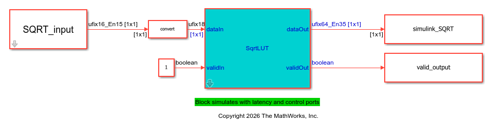
The SqrtLUT block computes the square root of an input signal by using a look-up table (LUT) and piecewise linear interpolation. Use this block for fixed-point signal processing applications where you need a high-speed square root operation with low latency and minimal resource usage. The SqrtLUT block normalizes input values outside the range [0,1] and then computes the square root by using piecewise linear interpolation based on the values in a lookup table. Finally, the block rescales the interpolated result and outputs it. For more information, see Compute Square Root Using Look-up Table Approach.
The block uses the validIn input port and validOut output port to indicate when the input data is valid and the output data is ready. Use these ports to simulate the block accurately with latency. The algorithm operates on a fixed-point format internally and maintains a fixed latency regardless of input data type. For more information, see Data Type Considerations.
To use this block in your Simulink® model, open the HDLMathLib library by entering this command
in the MATLAB® Command
Window:
open_system("HDLMathLib")Examples
This example shows how to compute the square root of fixed-point value and generate HDL code.
Create Data and Open Model
Create a variable that contains the data to compute. For this example, create a variable that contains a linear sweep. You can change these values according to your requirements.
SQRT_input = fi(1/2^15:1/2^15:1,0,16,15)';
Specify the word length for fixed-point data types and the latency for the model. The block maintains a fixed latency regardless of the input data type.
WL = 16;
latency = 7;
Open the hdlcoderSqrtLUT model and specify a stop time sufficient to process all the input combinations.
stoptime = length(SQRT_input)-1+latency;
open_system("hdlcoderSqrtLUT")
sim("hdlcoderSqrtLUT")
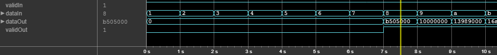
This figure shows the simulation waveform for the model. You can see that dataOut output is valid when validOut is 1, which is after 7 cycles.
Validate Simulink Output With Reference Value
To validate the output of the Simulink model, compare the output of the simulation to a reference value. Compute the reference output by using the sqrt function.
ref_SQRT = sqrt(double(SQRT_input));
Use logical indexing to extract the valid output.
implementation_SQRT = simulink_SQRT(valid_output);
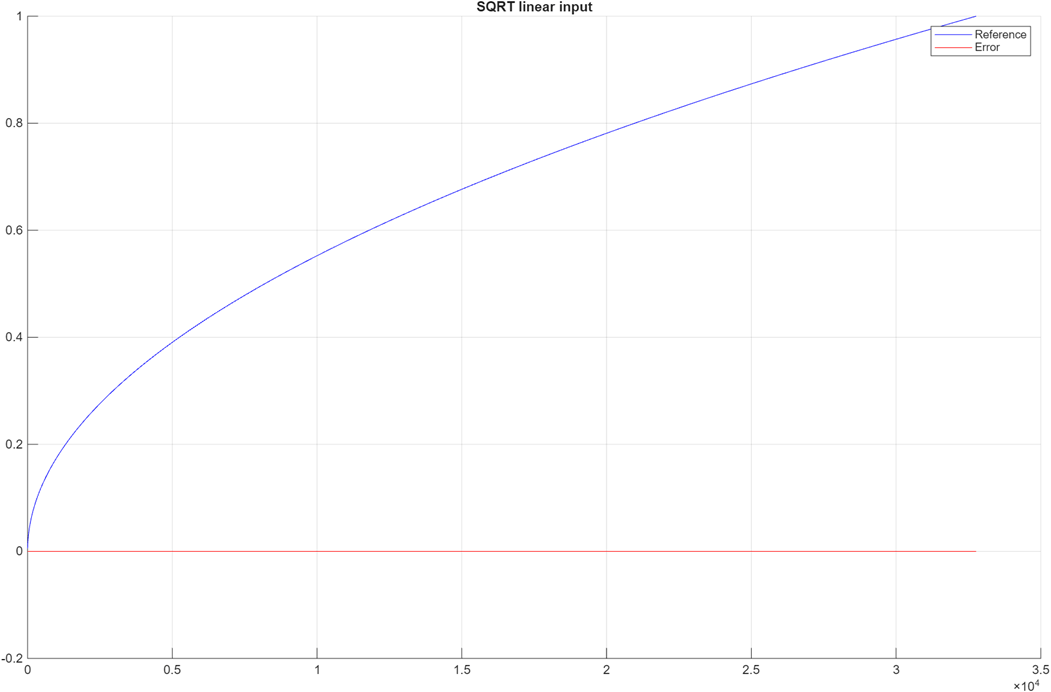
Plot the comparison results by using the comparison_plot_sqrt function. The maximum error value is significantly smaller than the output of the model.
comparison_plot_sqrtLUT(ref_SQRT,implementation_SQRT,1,"SQRT linear input");Maximum Error SQRT linear input 7.906744e-06 Maximum PctError SQRT linear input 1.358995e-03
Generate HDL Code for Square Root Implementation
Check the HDL settings of the model by using the hdlsaveparams function.
hdlsaveparams("hdlcoderSqrtLUT")%% Set Model 'hdlcoderSqrtLUT' HDL parameters
hdlset_param('hdlcoderSqrtLUT', 'Backannotation', 'on');
hdlset_param('hdlcoderSqrtLUT', 'HDLSubsystem', 'hdlcoderSqrtLUT/SqrtLUT');
hdlset_param('hdlcoderSqrtLUT', 'ProjectFolder', 'hdl_prj');
hdlset_param('hdlcoderSqrtLUT', 'ResetType', 'Synchronous');
hdlset_param('hdlcoderSqrtLUT', 'SynthesisTool', 'Xilinx Vivado');
hdlset_param('hdlcoderSqrtLUT', 'SynthesisToolChipFamily', 'Zynq UltraScale+');
hdlset_param('hdlcoderSqrtLUT', 'SynthesisToolDeviceName', 'xazu11eg-ffvf1517-1-i');
hdlset_param('hdlcoderSqrtLUT', 'TargetDirectory', 'hdl_prj\hdlsrc');
hdlset_param('hdlcoderSqrtLUT', 'TargetFrequency', 500);
hdlset_param('hdlcoderSqrtLUT', 'Traceability', 'on');
% Set Delay HDL parameters
hdlset_param('hdlcoderSqrtLUT/SqrtLUT/Linear_Interpolation/Delay12', 'ResetType', 'none');
% Set Delay HDL parameters
hdlset_param('hdlcoderSqrtLUT/SqrtLUT/Linear_Interpolation/Delay13', 'ResetType', 'none');
Generate HDL code for the model by using the makehdl function.
makehdl("hdlcoderSqrtLUT/SqrtLUT")### Working on the model hdlcoderSqrtLUT ### Generating HDL for hdlcoderSqrtLUT/SqrtLUT ### Using the config set for model hdlcoderSqrtLUT for HDL code generation parameters. ### Running HDL checks on the model 'hdlcoderSqrtLUT'. ### Begin compilation of the model 'hdlcoderSqrtLUT'... ### Begin compilation of the model 'hdlcoderSqrtLUT'... ### Working on the model 'hdlcoderSqrtLUT'... ### Working on... GenerateModel ### Begin model generation 'gm_hdlcoderSqrtLUT'... ### Copying DUT to the generated model.... ### Model generation complete. ### Generated model saved at hdl_prj/hdlsrc/hdlcoderSqrtLUT/gm_hdlcoderSqrtLUT.slx ### To highlight lookup tables mapped to RAM, click the following MATLAB script: hdl_prj/hdlsrc/hdlcoderSqrtLUT/highlightLUTPipeliningDiagnostic.m ### To clear highlighting, click the following MATLAB script: hdl_prj/hdlsrc/hdlcoderSqrtLUT/clearhighlighting.m ### Begin VHDL Code Generation for 'hdlcoderSqrtLUT'. ### Working on... Traceability ### Working on hdlcoderSqrtLUT/SqrtLUT/Linear_Interpolation as hdl_prj/hdlsrc/hdlcoderSqrtLUT/Linear_Interpolation.vhd. ### Working on hdlcoderSqrtLUT/SqrtLUT/Normalizer as hdl_prj/hdlsrc/hdlcoderSqrtLUT/Normalizer.vhd. ### Working on hdlcoderSqrtLUT/SqrtLUT/Variable_Right_Shift as hdl_prj/hdlsrc/hdlcoderSqrtLUT/Variable_Right_Shift.vhd. ### Working on hdlcoderSqrtLUT/SqrtLUT as hdl_prj/hdlsrc/hdlcoderSqrtLUT/SqrtLUT.vhd. ### Generating package file hdl_prj/hdlsrc/hdlcoderSqrtLUT/SqrtLUT_pkg.vhd. ### Code Generation for 'hdlcoderSqrtLUT' completed. ### Generating HTML files for code generation report at index.html ### Creating HDL Code Generation Check Report SqrtLUT_report.html ### HDL check for 'hdlcoderSqrtLUT' complete with 0 errors, 0 warnings, and 1 messages. ### HDL code generation complete.
close_system("hdlcoderSqrtLUT")
close all;
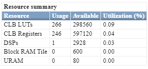
Resource Summary of SqrtLUT Block
Use the HDL Workflow Advisor to perform FPGA synthesis of your model. In the Workflow Advisor, select the target device and run the synthesis by navigating to FPGA Synthesis and Analysis > Perform Synthesis and P/R > Run Implementation task. Right-click the task and choose Run to Selected Task. The figure illustrates the synthesis performance of the SqrtLUT block on a Xilinx Zynq UltraScale+ device.
Limitations
You cannot use these data types as input values for the block:
Vectors, matrices, or buses
Complex numbers
Signed integers
Additionally, you cannot use input values that have more than 32 bits.
Ports
Input
Output
Parameters
More About
Algorithms
Extended Capabilities
Version History
Introduced in R2026a
See Also
Math Function | Sqrt | rSqrt | Sqrt