Airplane Tracking with ADS-B Captured Data
This example shows how to implement the Automatic Dependent Surveillance - Broadcast (ADS-B) receiver for HDL code generation and hardware implementation. This example decodes ADS-B extended squitter messages which can be used to track the airplane. The HDL-optimized model in this example uses Simulink® blocks that support HDL code generation to implement the ADS-B Receiver. This example model is used for real-time processing in HW/SW Co-Design Implementation of ADS-B Receiver Using Analog Devices AD9361/AD9364 (SoC Blockset), which requires the SoC Blockset™ Support Package for AMD® FPGA and SoC Devices.
Introduction
ADS-B is an air traffic management and control surveillance system. The broadcast messages (approximately once per second) contain the flight information including position and velocity. For introduction on ADS-B technology and modes of transmission, see [ 1 ]. The HDLRx subsystem is optimized for HDL code generation. The captured received signal is streamed into the receiver (HDLRx subsystem) front end. The streaming output of the receiver is buffered and passed to the MapResults MATLAB® function to view the output.
Structure of the Example
The model supports both Normal and Accelerator modes. The top-level structure of the ADS-B receiver model is shown in the following figure.
![]()
The receiver input data is captured using HW/SW Co-Design Implementation of ADS-B Receiver Using Analog Devices AD9361/AD9364 (SoC Blockset) running on the Zynq® platform. The captured data represents the baseband received signal with a sampling rate of 4 MHz. The data contains 8 frames of extended squitter messages. The ADS-B transmitter modulates the 112-bit extended squitter messages using 2-bit pulse-position modulation, and adds a 16-bit prefix. Then, to generate 4 MHz data, each 240-bit message is zero-padded and upsampled by 2.
This diagram shows the detailed structure of the HDLRx subsystem.
![]()
The subsystems listed here are described further in the following sections.
1. Magnitude Calculation - Finds the complex modulus of the received input signal
2. Threshold Calculation - Calculates the threshold value based on received input signal strength
3. Correlation with Preamble - Correlates the received signal with reference signal to detect the preamble
4. Timing Control - Provides timing synchronization for the receiver
5. Bit Process - Decodes symbols using PPM demodulation
6. Compute CRC and Frame Validation - Validates the frame by checking for CRC errors
HDL Optimized ADS-B Receiver
1. Magnitude Calculation
The inputs to the Magnitude Calculation subsystem are the in-phase (real) and quadrature (imaginary) phase samples. This subsystem outputs the modulus of the complex number. The ![]() can be approximated by the
can be approximated by the ![]() algorithm described on page 238 of [ 2 ].
algorithm described on page 238 of [ 2 ].
![]()
where
![]() is the larger value of
is the larger value of ![]() or
or ![]()
and ![]() is the smaller value of
is the smaller value of ![]() or
or ![]() .
.
The Gain block converts received input from 12-bit to 16-bit word length.
![]()
For the implementation of ![]() algorithm, see the following model.
algorithm, see the following model.
![]()
2. Threshold Calculation
The Threshold Calculation subsystem calculates the signal energy and applies a scaling factor to create a threshold for preamble detection. Moving Average Filter is a serial FIR filter architecture with 32 coefficients that operates on the magnitude values. The coefficients of the FIR filter are selected to find the average energy of the received signal. This example scales the signal energy by 5 to detect valid ADS-B preambles. For details on FIR filter, see Discrete FIR Filter.
![]()
3. Correlation with Preamble
The Correlation with Preamble subsystem correlates the received signal with the ADS-B reference/preamble sequence [1 0 1 0 0 0 0 1 0 1 0 0 0 0 0 0] using a peak detection filter. The peak detection filter is a serial FIR Filter architecture, configured with coefficients that match the preamble sequence. Preamble correlation identifies potential ADS-B transmissions and aligns our bit detection algorithm with the first message bit. The preamble is detected if the peak amplitude exceeds the scaled threshold value. Once the preamble is detected, the correlation value is passed on as input(SyncCorr) to the Timing Control block.
![]()
4. Timing Control
The Timing Control block is a state machine that detects the preamble and generates the control signals ActivateBP and Reset, that indicate the start of frame, end of frame and reset status to the Bit Process and Compute CRC and Frame Validation blocks.
5. Bit Process
The Bit Process subsystem demodulates and down converts the 4 MHz received signal to a 1 MHz bit sequence. Each data bit is represented by four PPM bits. To demodulate, the block finds the sum of the first two bits and the last two bits of each quadruplet. Then, it compares the sums to determine the original bit value. The output valid signal is asserted every fourth cycle to align with 1 MHz bit sequence.
![]()
6. Compute CRC and Frame Validation
This subsystem checks for mismatches in the 24-bit checksum of each 88-bit message. The CRC block needs an indication of the frame boundaries to determine which bits are the checksum. The rising edge of the ActivateBP signal generated from the Timing Control block indicates the start of frame, and the falling edge indicates the end of the frame. The start signal is delayed to match the demod latency. When the block output err signal is zero, the frame is a valid ADS-B message. The subsystem buffers the message bits until the message is confirmed to have no CRC error.
![]()
Launch Map and Log Data
You can launch the map and start text file logging using the two slider switches (Launch Map and Data Logging).
Launch Map - Launch the map where the tracked flights can be viewed. NOTE: You must have a Mapping Toolbox™ license to use this feature.
Data Logging - Save the captured data in a TXT file. You can use the saved data for later for post processing.
Results and Displays
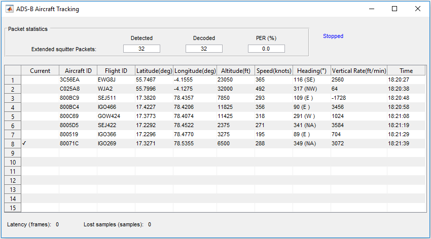
The HDLRx subsystem demodulates and decodes the ADS-B data and the output is streamed through Deserializer1D block and MapResults MATLAB function, which produces hexadecimal output information about the aircraft. Each extended squitter Mode S packet contains partial information (any of Aircraft ID, Flight ID, Altitude, Speed, and Location) about the aircraft and the table is built up from multiple messages. The output is obtained as shown in the following diagram. The packet statistics include the number of detected packets, the number of correctly decoded packets, and packet error rate (PER). These aircraft details match the transmitted values from the HW/SW Co-Design Implementation of ADS-B Receiver Using Analog Devices AD9361/AD9364 (SoC Blockset) example.
HDL Code Generation and Synthesis Results
Pipeline registers have been added to the model to make sure that HDLRx subsystem does not have a long critical path. The HDL code generated from the HDLRx subsystem was synthesized using Vivado® on a Zynq® FPGA with the device 7z045ffg900-2, and the design achieves 251.2 MHz clock frequency, which is sufficient to decode the real-time ADS-B signals. The generated HDL code is tested and verified in the real-time example HW/SW Co-Design Implementation of ADS-B Receiver Using Analog Devices AD9361/AD9364 (SoC Blockset). To check and generate the HDL code referenced in this example, you must have an HDL Coder™ license. The following table shows the synthesis results of this example.
         Resources          Values
    ____________________    ______

    Slice LUT               1655
    Slice Registers         4810
    RAMB36                  0
    DSP                     2
    Max. Frequency (MHz)    251.2
References
International Civil Aviation Organization, Annex 10, Volume 4. Surveillance and Collision Avoidance Systems.
Marvin E. Frerking, Digital Signal Processing in Communication Systems, Springer Science Business Media, New York,1994.