Generate Clock Enable Signals
HDL Coder™ generates clock enable signals that control the specific operations or
blocks in a Simulink design are active. By using clock enable signals, HDL Coder
translates high-level Simulink® models or MATLAB® code into optimized HDL code, and ensures that the necessary operations
are performed at each clock cycle. The code generator generates two clock enable
signals, the clock enable input signal, clk_enable, and the clock
enable output signal, ce_out. The generation of clock enable signals
varies depending on whether the model is single rate or multirate.
Single-rate and Multirate Models
During HDL code generation, HDL Coder creates clock-related signals,
clk (clock), reset, and
clk_enable (clock enable). These signals are automatically
inserted into the generated HDL code. HDL Coder generates
clk_enable signals based on sample time and target frequency.
The clock enable signals control when logic is active, simulating the sample time
behavior.
Single-rate models:
If all blocks share the same sample time, HDL Coder generates a single clock domain.
The generated HDL code includes a single
clksignal and optionally aclk_enablesignal if needed.
Multirate models:
Some optimizations such as resource sharing or pipelining, and blocks such as Upsample, Downsample, Rate Transition, introduce multiple sample rates.
If blocks have different sample times, HDL Coder generates a timing controller in the single-clock mode.
This controller uses a base clock and generates clock enable signals for each slower rate.
HDL Coder maps the fastest generated sample time to base clock cycle.
These enables control when each block operates, simulating multiple clock domains using a single clock.
Single or Multiple Clock Inputs in Multirate Models
If your model has multiple rates, you can configure the Clock
inputs parameter to either Single or
Multiple in HDL Code Generation > Global
Settings > Clock Settings.
Single clock input:
One clock input is generated for the entire design.
If your model is multirate, HDL Coder:
Uses the fastest sample time as the base clock.
Generates clock enable signals for slower sample rates.
Synthesizes a timing controller to manage the clock enable signals.
Use this setting for most designs due to simplicity and compatibility with synthesis tools.
Multiple clock inputs:
HDL Coder generates a separate clock input for each Simulink rate in the design under test (DUT).
When you use multiple clock inputs:
The Oversampling factor must be 1.
Each Simulink rate must include sequential logic (e.g., Delay blocks) to trigger clock generation.
Use this setting only when your hardware architecture requires distinct clock domains.
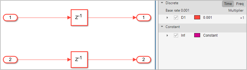
Clock Enable Signals in Single-Rate Models
By default, a model operates at a single rate, which means each sample time unit
in Simulink corresponds to one clock cycle in the HDL code. In this figure, the
two Delay blocks operate at the same sample rate. For single-rate models, HDL Coder
generates one clock enable input and one clock enable output signals. The
clk_enable input signal controls timing operation at the base
rate. The HDL coder feeds the clk_enable to the
ce_out.
ENTITY DUT IS
  PORT( clk                               :   IN    std_logic;
        reset                             :   IN    std_logic;
        clk_enable                        :   IN    std_logic;
        In1                               :   IN    std_logic_vector(7 DOWNTO 0);  -- int8
        In2                               :   IN    std_logic_vector(7 DOWNTO 0);  -- uint8
        ce_out                            :   OUT   std_logic;
        Out1                              :   OUT   std_logic_vector(7 DOWNTO 0);  -- int8
        Out2                              :   OUT   std_logic_vector(7 DOWNTO 0)  -- uint8
        );
END DUT;

...

ce_out <= clk_enable;
Clock Enable Signals in Multirate Models
A model is multirate when it contains blocks that run at different sample rates or when you apply HDL optimizations such as streaming, sharing, oversampling, or clock-rate pipelining to a single-rate model. In a multirate model, HDL Coder generates a timing controller entity that defines the timing signals for the model. The timing controller generates clock enables for various rates. The name of clock enable signals include necessary rate and phase information needed to manage the clocking for the design. The timing controller generates clock enable signals based on the settings of the Clock inputs and Timing controller architecture parameters.
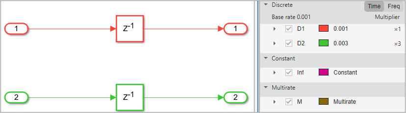
Multirate Model with Single Clock Mode
When your model is multirate and the Clock inputs
parameter is Single, HDL Coder generates a timing
controller that handles clocking for different rates.
In this figure, the Delay blocks operate at different sample rates. HDL Coder can generate the timing controller entity either in the DUT or externally, depending on the Timing controller architecture parameter. For more information, see Timing controller architecture.
When you set the Timing controller architecture parameter
to Default or Resettable,
HDL Coder generates the timing controller within the DUT. The timing
controller entity employs a single primary clock input that
corresponds to the base rate of the DUT, which is the fastest rate in the model.
It generates single clk_enable input signal that controls the
timing at the base rate and also generates multiple ce_out
output signals, ce_out_0 and ce_out_1, for
the different rates. The HDL Coder feeds ce_out_0 from the
clk_enable corresponding to the base rate.
ce_out_1 is a phased clock enable that drives the
operations for the slower rates. For more information, see Timing Controller for Multirate Models.
ENTITY DUT IS
  PORT( clk                               :   IN    std_logic;
        reset                             :   IN    std_logic;
        clk_enable                        :   IN    std_logic;
        In1                               :   IN    std_logic_vector(7 DOWNTO 0);  -- int8
        In2                               :   IN    std_logic_vector(7 DOWNTO 0);  -- int8
        ce_out_0                          :   OUT   std_logic;
        ce_out_1                          :   OUT   std_logic;
        Out1                              :   OUT   std_logic_vector(7 DOWNTO 0);  -- int8
        Out2                              :   OUT   std_logic_vector(7 DOWNTO 0)  -- int8
        );
END DUT;

...

  u_DUT_tc : DUT_tc
    PORT MAP( clk => clk,
              reset => reset,
              clk_enable => clk_enable,
              enb => enb,
              enb_1_1_1 => enb_1_1_1,
              enb_1_2_0 => enb_1_2_0,
              enb_1_2_1 => enb_1_2_1
              );

...

  ce_out_0 <= enb_1_1_1;

  ce_out_1 <= enb_1_2_1;
When you set the Timing controller architecture parameter
to external, HDL Coder generates the timing
controller externally and exposes the clock enable from the top-level design.
You can use this setting to integrate a custom external timing controller into
the design. The DUT has a single clock input and multiple clock enable inputs
for each rate.
ENTITY DUT IS
  PORT( clk                               :   IN    std_logic;
        reset                             :   IN    std_logic;
        enb                               :   IN    std_logic;
        enb_1_1_1                         :   IN    std_logic;
        enb_1_2_0                         :   IN    std_logic;
        enb_1_2_1                         :   IN    std_logic;
        In1                               :   IN    std_logic_vector(7 DOWNTO 0);  -- int8
        In2                               :   IN    std_logic_vector(7 DOWNTO 0);  -- int8
        ce_out_0                          :   OUT   std_logic;
        ce_out_1                          :   OUT   std_logic;
        Out1                              :   OUT   std_logic_vector(7 DOWNTO 0);  -- int8
        Out2                              :   OUT   std_logic_vector(7 DOWNTO 0)  -- int8
        );
END DUT;

...

  ce_out_0 <= enb_1_1_1;

  ce_out_1 <= enb_1_2_1;
Multirate Model with Multiple Clock Mode
When your model is multirate and Clock inputs parameter
is Multiple, HDL Coder generates separate clock
inputs for each rate in the model, which allows each clock signal to drive its
own rate. There is no primary clock rate in this mode, so each rate operates
independently. The generated HDL code employs clock enable signals that
correspond to their respective clock inputs for each rate. The code generator
does not generate ce_out signals in this mode because the
clk_enable signals control timing operations for the
different clock rates.
ENTITY DUT IS
  PORT( clk                               :   IN    std_logic;
        clk_1_2                           :   IN    std_logic;
        reset                             :   IN    std_logic;
        reset_1_2                         :   IN    std_logic;
        clk_enable                        :   IN    std_logic;
        clk_enable_2                      :   IN    std_logic;
        In1                               :   IN    std_logic_vector(7 DOWNTO 0);  -- int8
        In2                               :   IN    std_logic_vector(7 DOWNTO 0);  -- int8
        Out1                              :   OUT   std_logic_vector(7 DOWNTO 0);  -- int8
        Out2                              :   OUT   std_logic_vector(7 DOWNTO 0)  -- int8
        );
END DUT;
When your DUT contains downsampling operations that require a clock divider, HDL Coder generates a timing controller. The timing controller uses several clock dividers that depends on the number of unique downsampling requests across the various rates. The outputs of the timing controller are clock enable signals that operate at rates that are integer multiples slower than the primary clock of the timing controller.
ENTITY DUT IS
  PORT( clk                               :   IN    std_logic;
        clk_1_2                           :   IN    std_logic;
        reset                             :   IN    std_logic;
        reset_1_2                         :   IN    std_logic;
        clk_enable                        :   IN    std_logic;
        clk_enable_2                      :   IN    std_logic;
        In1                               :   IN    std_logic_vector(7 DOWNTO 0);  -- int8
        Out1                              :   OUT   std_logic_vector(7 DOWNTO 0)  -- int8
        );
END DUT;

...

  u_DUT_tc : DUT_tc
    PORT MAP( clk => clk,
              reset => reset,
              clk_enable => clk_enable,
              enb => enb,
              enb_r1_1_2_1 => enb_r1_1_2_1
              );

...
If the multirate model contains downsampling operations and the rate domains intersect and are not integer multiples, you can use the AsyncRTAsWire HDL block property to generate a wire for the Rate Transition block when these asynchronous rates are present. By enabling this option, you can prevent HDL Coder from generating clock dividers for asynchronous sample rates.