Rate Transition
Handle transfer of data between blocks operating at different rates
Libraries:
Simulink /
Signal Attributes
HDL Coder /
Signal Attributes
Description
The Rate Transition block transfers data from the output of a block operating at one rate to the input of a block operating at a different rate. Use the block parameters to trade data integrity and deterministic transfer for faster response or lower memory requirements. To learn about data integrity and deterministic data transfer, see Data Transfer Considerations (Simulink Coder).
Transition Handling Behaviors
| Behavior | Parameter Settings | Notes |
|---|---|---|
| Select:
|
|
| Select:
Clear:
|
|
| Clear:
|
|
The behavior of the Rate Transition block depends on:
Sample times of the ports to which the block connects (see Effects of Synchronous Sample Times and Effects of Asynchronous Sample Times)
Priorities of the tasks for the source and destination sample times (see Sample time properties)
Whether the model specifies a fixed- or variable-step solver (see Compare Solvers)
Setting of model configuration parameters Device vendor and Device type (see Effects of Device Configuration)
Block Labels
When you update a model diagram, a label appears on the Rate Transition block to indicate simulation behavior.
| Label | Block Behavior |
|---|---|
ZOH
| Acts as a zero-order hold |
1/z
| Acts as a unit delay |
Buf
| Copies input to output under semaphore control |
Db_buf
| Copies input to output by using double buffers |
3buf | Copies input to output by using triple buffers |
Copy
| Unprotected copy of input to output |
NoOp
| No operation |
Mixed
| Expands to multiple blocks with different behaviors |
RT | Indicates data transfer between partitions when using the Schedule Editor. For more information, see Using the Schedule Editor. |
Memory | Memory label depends on the data type that is provided as an input to the Rate Transition block. The block is in memory mode when Ensure deterministic data transfer (maximum delay) is cleared. |
The block behavior label shows the method that ensures safe transfer of data between tasks operating at different rates. You can use the sample-time colors feature (see View Sample Time Information) to display the relative rates that the block bridges. Consider this example model:
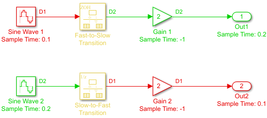
Sample-time colors and the block behavior labels show:
The Rate Transition block at the top of the diagram acts as a zero-order hold in a fast-to-slow transition.
The Rate Transition block at the bottom of the diagram acts as a unit delay in a slow-to-fast transition.
For more information, see Data Transfer Representation and Processing (Simulink Coder).
For the Memory label, the Rate Transition operates in a memory mode if the data type
that is an input to the Rate Transition block is the same size, smaller than, or equal to
the largest atomic size, then the data can be safely copied in a single atomic operation.
If the input data type is larger than the Largest Atomic Size, then the rate transition
needs to double buffer mode Db_buf, to ensure data integrity under all
possible circumstances.
Effects of Synchronous Sample Times
This table summarizes how each label appears when the sample times of the input and
output ports (inTs and outTs) are periodic, or
synchronous.
Block Settings | Block Label | |||
|---|---|---|---|---|
Rate Transition | Conditions for Rate Transition Block | With Data Integrity and Determinism | With Only Data Integrity | Without Data Integrity or Determinism |
(Equal) |
| None (error) |
|
|
|
|
| ||
| None (error) |
| ||
(Fast to slow) |
|
|
Buf
| |
| None (error) | |||
| None (error) |
Db_buf
| ||
| None (error) | |||
(Slow to fast) |
|
|
Db_buf
| |
| None (error) | |||
| None (error) | |||
| None (error) | |||
KEY
| ||||
Note
When you select model configuration parameter Block reduction,
Copy reduces to NoOp. No code generation occurs
for a Rate Transition block with a NoOp label. To
prevent a block from being reduced when block reduction is on, add a test point to the
block output (see Configure Signals as Test Points).
For labels 3Buf, Mixed, and RT,
the effect of synchronous sample time is as follows:
| Label | Effect of Synchronous Sample Time |
|---|---|
3Buf | No effect. Triple-buffer copies apply for multicore scenarios only. |
Mixed | Each element of a virtual bus includes a hidden rate transition. The behavior of the rate transition for the individual bus elements can differ. |
RT | Target-specific critical-section protection is not needed. |
Effects of Asynchronous Sample Times
This table summarizes how each label appears when the sample time of the input or output
port (inTs or outTs) is not periodic, or
asynchronous.
Block Settings | Block Label | |||
|---|---|---|---|---|
| With Data Integrity and Determinism | With Only Data Integrity | Without Data Integrity or Determinism | ||
|
|
|
| |
| None (error) |
| ||
KEY
| ||||
Effects of Device Configuration
If the settings of model configuration parameters Device vendor and Device type specify hardware that supports atomic data load and store operations, the code generator optimizes the generated rate transition code when the target hardware supports atomic load and store operations for the data type of the signal being transferred. The code generator takes advantage of the hardware data load and store capability by replacing double-buffering code between asynchronous tasks with code that performs a single memory copy.
Ports
Input
Output
Parameters
Block Characteristics
Data Types |
|
Direct Feedthrough |
|
Multidimensional Signals |
|
Variable-Size Signals |
|
Zero-Crossing Detection |
|