Select TLM Mapping Options
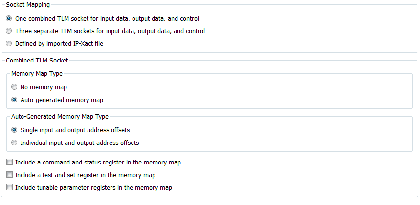
Select socket and memory map configuration for your TLM component on the TLM Mapping tab. You can select a single socket, or three sockets, generated from your Simulink® model, or choose to import a custom socket map using an IP-XACT file. If you select one of the fixed socket configurations, you can specify additional memory map options.
Socket Mapping
You can choose to have a single, combined TLM socket for input data, output data, and control or you can choose three separate TLM socket for input data, output data, and control so that you can connect the sockets to different buses. Alternatively, you can customize the socket mapping using an IP-XACT file.
One combined TLM socket for input data, output data, and control — Selecting this option displays the Combined TLM Socket parameters to configure the generated memory map. See Memory Map Configuration.
Three separate TLM sockets for input data, output data, and control — Selecting this option displays separate memory map parameters for the three sockets. See Memory Map Configuration.
Defined by imported IP-XACT file — When prompted, provide the path and file name of the IP-XACT file.

See Prepare IP-XACT File for Import for IP-XACT file requirements.
By default, only those registers and signal ports mapped to Simulink signals are implemented in the generated TLM component. Select Generate code for unmapped IP_XACT registers/bitfields to include all registers from the IP-XACT file in the generated TLM component. Select Generate code for unmapped IP_XACT signal ports to include all signal ports from the IP-XACT file in the generated TLM component.
When you import an IP-XACT file, you can optionally generate an interface compatible with the System C Modeling Library (SCML). Select Implement memory map with SCML. See Implement Memory Map with SCML. To use this feature, you must install SCML from Synopsys®.
Memory Map Configuration
For each socket, choose the socket mapping type. For a description of the options available under Memory Map Type, see Memory Mapping.
If you choose Auto-generated memory map, the options expand to include the Auto-Generated Memory Map Type section, as shown in the following figures:
| Single TLM Socket | Separate TLM Sockets |
|---|---|
|
|
Select the autogenerated memory map type for each TLM socket:
Single input and output address offsets — See Automatically Generated Memory Map with Single Address.
Individual input and output address offsets — See Automatically Generated Memory Map with Individual Addresses.
For the control socket (either separate or combined), select any of the following options:
Include a command and status register in the memory map — See Registers and Signal Ports.
Include a test and set register in the memory map — See Test and Set Register.
Include tunable parameter registers in the memory map —The tunable parameter registers allow you to adjust the TLM component before or during simulation.

