Contenuto principale

Pressure-Compensated 3-Way Flow Control Valve (IL)

R2026b

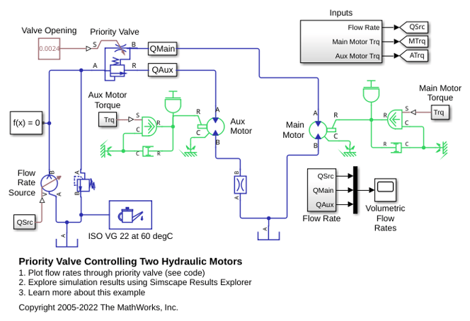
3-way flow control in an isothermal liquid system

  • Pressure-Compensated 3-Way Flow Control Valve (IL) block

Libraries:
Simscape / Fluids / Isothermal Liquid / Valves & Orifices / Flow Control Valves

Description

The Pressure-Compensated 3-Way Flow Control Valve (IL) block models constant-pressure flow control. When the control pressure, pApB, meets or exceeds the Set orifice pressure differential, the relief component of the underlying compensator valve opens to maintain the pressure in the block.

The flow control valve opening and closing is controlled by a physical signal received at port S, which determines the area of the underlying orifice block. A positive signal opens the valve. Port R vents liquid to another part of your network.

For pressure-compensated flow control without venting, see the Pressure-Compensated Flow Control Valve (IL) block.

Orifice Parameterization

You can choose the valve model with the Orifice parameterization setting:

  • Linear - area vs. control member position is an analytical formulation that assumes the valve opening area and the valve control member are related linearly.

  • Tabulated data - Area vs. control member position is a user-supplied data sheet that relates orifice opening area and the control member position. The block queries between data points with linear interpolation and uses nearest extrapolation for points beyond the table boundaries.

  • Tabulated data - Volumetric flow rate vs. control member position and pressure drop is a user-supplied data sheet that relates the control member position, orifice pressure drop, and orifice volumetric flow rate. The block queries between data points with linear interpolation and uses a nearest extrapolation for points beyond the table boundaries.

Numerically-Smoothed Area and Pressure

When the orifice parameterization is linear, you can maintain numerical robustness at the extremes of the orifice area and valve pressure range by tuning the Smoothing factor parameter to a nonzero value less than 1. If the Smoothing factor parameter is nonzero, the block applies a smoothing function to all calculated areas and pressures, but it primarily influences the simulation at the extremes of these ranges.

If you enable smoothing, the block smoothly saturates the orifice area between the Leakage area and Maximum orifice area parameters. The block smoothly saturates the valve pressure between the Set orifice pressure differential parameter and the sum of the Set orifice pressure differential and the Pressure compensator valve regulation range parameters.

For more information, see Numerical Smoothing.

Block Schematic

The Pressure-Compensated 3-Way Flow Control Valve (IL) is constructed from the Pressure Compensator Valve (IL) and Orifice (IL) blocks.

Three-Way Flow Control Valve Schematic

Block composite diagram

Examples

Ports

Conserving

expand all

Liquid entry or exit port to the three-way valve.

Programmatic Use

Port: A

Liquid entry or exit port to the orifice.

Programmatic Use

Port: B

Liquid exit port from the reducing valve.

Programmatic Use

Port: R

Input

expand all

Orifice opening in m, set as a physical signal.

Programmatic Use

Port: S

Parameters

expand all

Method of modeling the opening of the orifice. The opening is either parametrized linearly, which correlates the opening area to the control member position; by user-supplied data that correlate the orifice opening area to the control member position; or by an array of data that correlates the valve flow rate to the control member position and valve pressure drop.

Programmatic Use

Parameter: orifice_spec
Values: "fluids.isothermal_liquid.valves_orifices.orifices.enum.orifice_spec.linear" | "fluids.isothermal_liquid.valves_orifices.orifices.enum.orifice_spec.table1D_area_opening" | "fluids.isothermal_liquid.valves_orifices.orifices.enum.orifice_spec.table2D_volflow_opening_pressure"

Control member offset when the orifice is fully open. A positive, nonzero value indicates a partially closed orifice. A negative, nonzero value indicates an overlapped orifice that remains open for an initial displacement set by the physical signal at port S.

Programmatic Use

Parameter: S_min

Control member stroke that fully opens the orifice.

Dependencies

To enable this parameter, set Orifice parameterization to Linear - area vs. control member position.

Programmatic Use

Parameter: del_S

Cross-sectional area of the orifice in its fully open position. This parameter is used as an upper limit for area-pressure calculations during the simulation.

Dependencies

To enable this parameter, set Orifice parameterization to Linear - area vs. control member position.

Programmatic Use

Parameter: area_max

Vector of orifice opening distances for the tabular parameterization of the orifice opening area. The vector elements must correspond one-to-one with the elements in the Orifice area vector parameter. The elements are listed in ascending order and the first element must be 0. Linear interpolation is employed between table data points.

Dependencies

To enable this parameter, set Orifice parameterization to Tabulated data - Area vs. control member position.

Programmatic Use

Parameter: S_TLU

Vector of valve opening areas for the tabular parameterization of the valve opening area. The vector elements must correspond one-to-one with the elements in the Control member position vector parameter. The elements are listed in ascending order and must be greater than 0. The first element of this vector is the leakage area.

Dependencies

To enable this parameter, set Orifice parameterization to Tabulated data - Area vs. control member position.

Programmatic Use

Parameter: orifice_area_TLU

Vector of control member positions for the tabular parameterization of the volumetric flow rate. The control member position vector forms an independent axis with the Pressure drop vector, dp parameter for the 3-D dependent Volumetric flow rate table, q(s,dp) parameter. A positive displacement corresponds to valve opening. The values are listed in ascending order and the first element must be 0. Linear interpolation is employed between table data points.

Dependencies

To enable this parameter, set Orifice parameterization to Volumetric flow rate vs. control member position and pressure drop.

Programmatic Use

Parameter: S_vol_flow_TLU

Vector of valve opening areas for the tabular parameterization of the valve opening area. The pressure drop vector forms an independent axis with the Control member position vector, s parameter for the 3-D dependent Volumetric flow rate table, q(s,dp) parameter. The values are listed in ascending order and must be greater than 0. Linear interpolation is employed between table data points.

Dependencies

To enable this parameter, set Orifice parameterization to Volumetric flow rate vs. control member position and pressure drop.

Programmatic Use

Parameter: p_diff_TLU

Array of volumetric flow rates based on independent values of pressure drop and spool travel distance. M and N are the sizes of the corresponding vectors:

  • M is the number of elements in the Pressure drop vector, dp parameter.

  • N is the number of elements in the Control member position vector, s parameter.

Dependencies

To enable this parameter, set Orifice parameterization to Volumetric flow rate vs. control member position and pressure drop.

Programmatic Use

Parameter: vol_flow_TLU

Magnitude of pressure differential that triggers valve opening or closing.

Programmatic Use

Parameter: p_diff_orifice

Cross-sectional area of the valve in its fully open position. This parameter is used as an upper limit for area-pressure calculations during the simulation.

Programmatic Use

Parameter: p_range

Operational pressure range of the valve. The pressure regulation range lies between the Set orifice pressure differential and the maximum valve operating pressure.

Programmatic Use

Parameter: area_max_compensator

Sum of all gaps when the valve is in the fully closed position. Any area smaller than this value is maintained at the specified leakage area. This contributes to numerical stability by maintaining continuity in the flow.

Programmatic Use

Parameter: area_leak

Correction factor that accounts for discharge losses in theoretical flows.

Programmatic Use

Parameter: Cd

Upper Reynolds number limit for laminar flow through the valve.

Programmatic Use

Parameter: Re_c

Continuous smoothing factor that introduces a layer of gradual change to the flow response when the valve is in near-open or near-closed positions. Set this value to a nonzero value less than one to increase the stability of your simulation in these regimes.

Programmatic Use

Parameter: smoothing_factor

Extended Capabilities

expand all

C/C++ Code Generation
Generate C and C++ code using Simulink® Coder™.

Version History

Introduced in R2020a