Main Content

Hall Validity

Compute rotor spin direction and validity of Hall sensor sequence

Since R2020a

Libraries:
Motor Control Blockset / Sensor Decoders

Description

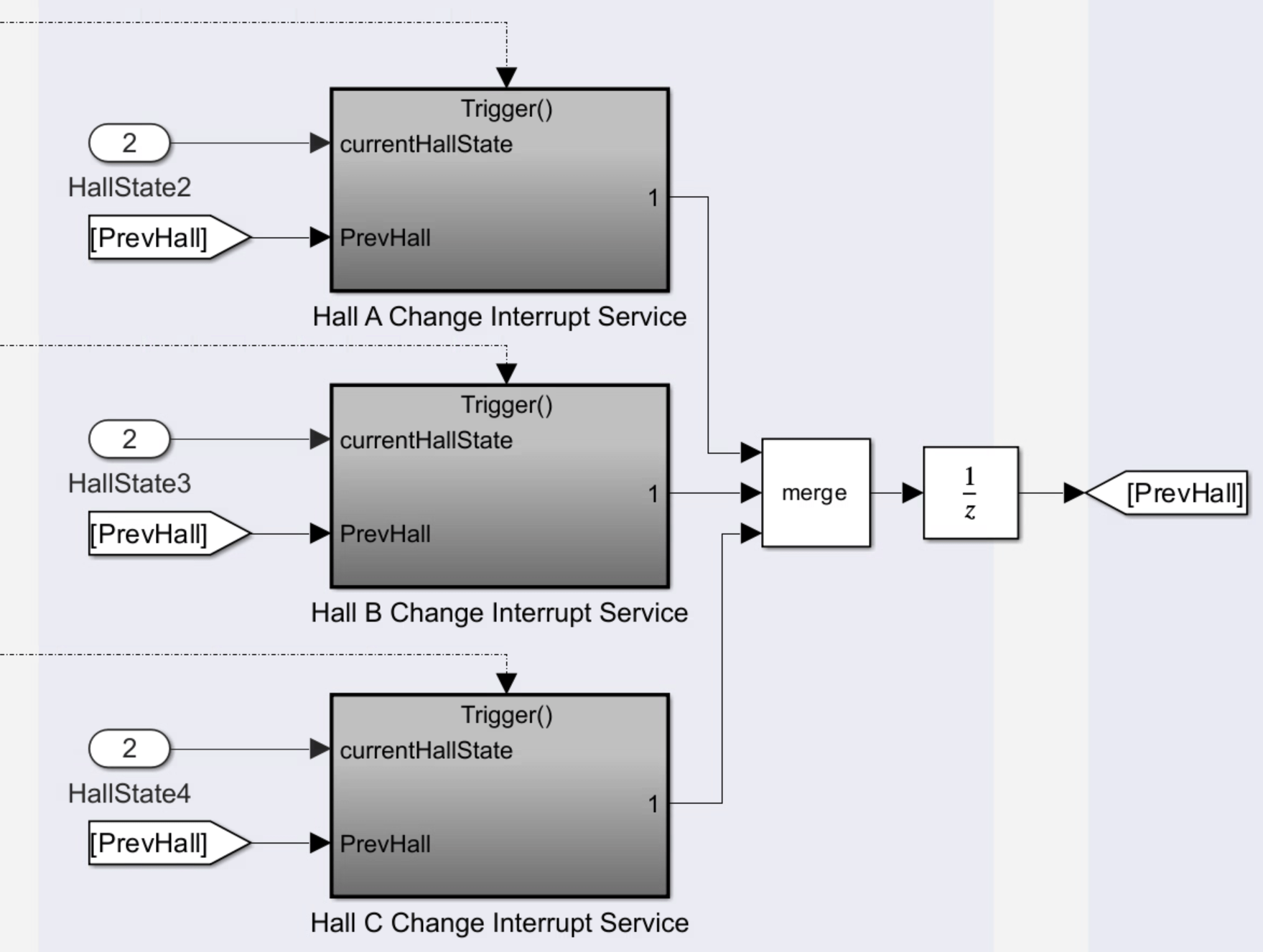
The Hall Validity block checks and validates every state of the Hall sensor output sequence. The block identifies the condition when one or more Hall sensors are in an invalid state.

The block executes when a Hall sensor output state (or Hall state) changes.

Ports

Input

expand all

The Hall state at current time. These are the possible input values (three-bit numbers where the MSB represents the output of the first Hall connected):

  • 5 - (101)

  • 4 - (100)

  • 6 - (110)

  • 2 - (010)

  • 3 - (011)

  • 1 - (001)

Note

The output port Invalid indicates a bad hall sensor condition.

Data Types: uint8 | uint16 | uint32

The Hall state prior to the current state.

Data Types: uint8 | uint16 | uint32

The external counter value that the block uses to determine the time elapsed between the Hall state change and block execution.

Note

The counter must reset when a Hall state changes.

Data Types: uint8 | uint16 | uint32

The direction of rotor spin (either +1 or -1 indicating positive or negative direction of rotation, respectively) during the previous Hall state.

Data Types: uint8 | uint16 | uint32

Output

expand all

The indicator of Hall sensor validity during the current or previous Hall state. The block checks the validity of the sensors by comparing the values of the HallVal and PrevHallVal input port with the value of the Expected hall sequence in positive direction parameter. The port can output these values:

  • 1 – (001) Indicates that one (or more) sensors are bad.

  • 0 – (000) Indicates that all sensors are good.

Data Types: single | double | fixed point

The value of the Cnt input port when a Hall state changes.

Note

The counter must reset when a Hall state changes. Therefore, this port indicates the number of counts during the previous Hall state.

Data Types: single | double | fixed point

The direction of the rotor spin (either +1 or –1 indicating positive or negative direction of rotation, respectively) during the current Hall state. The block computes the direction by comparing the values of the HallVal and PrevHallVal input ports with the value of the Expected hall sequence in positive direction parameter.

Data Types: single | double | fixed point

The port outputs zero when either one or both conditions occur:

  • The block detects a bad hall sensor state (in either HallVal or PrevHallVal input port values).

  • The block detects a change in the rotor spin direction.

The zero value indicates that you cannot calculate the valid speed for the current Hall state because the current value of SpdCnt is invalid. The port outputs the value one to indicate that a valid speed calculation is possible.

Data Types: single | double | fixed point

The port outputs the value one (and sets the Hall state change flag to one) after the Hall state changes and the block has completed execution.

Data Types: single | double | fixed point

Parameters

expand all

The Hall sensor sequence that represents the positive direction of rotor spin.

The custom sequence that you can enter to represent rotor spin in the positive direction.

Dependencies

To enable this parameter, set Expected hall sequence in positive direction to Custom sequence.

The register size of the external counter. The maximum counter value is 2n-1, where n = counter size.

Extended Capabilities

C/C++ Code Generation
Generate C and C++ code using Simulink® Coder™.

Fixed-Point Conversion
Design and simulate fixed-point systems using Fixed-Point Designer™.

Version History

Introduced in R2020a