Design and Evaluate SAR ADC
This example shows how to design a SAR ADC using reference architecture and validate the ADC using ADC Testbench.
Set UP SAR ADC Testbench Model
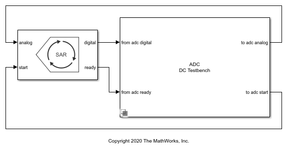
Open the model SAR_ADC attached to this example as a supporting file. The model consists of a SAR ADC block and an ADC Testbench.
open_system('SAR_ADC.slx')
ADC Specifications and Impairments
Double click the SAR ADC block to open the Block Parameters dialog box. The Number of bits is set to 10, and the SAR Frequency is 2e7 Hz. Check that in the Impairments tab, impairments are enabled. Set the Offset error to 0.65 LSB and Gain error to 0.65 LSB. The specifications are taken from the datasheet of Analog Devices 10-bit SAR ADC AD 7298.
Modify ADC Testbench According to ADC Specification
Double click the ADC Testbench block to open the Block Parameters dialog box. The Measurement option is selected as DC and the Error tolerance is 0.01 LSB. In the Setup tab, click the Autofill setup parameters button to automatically propagate the ADC parameters to the testbench. In the Target Metric tab, click the Autofill target metric button to automatically propagate the ADC target metrics to the testbench. Save the changes.
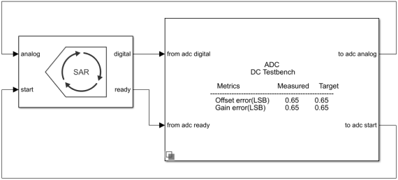
Plot DC Analysis Results
Run the simulation for 0.2048 s. The measured and target values of offset error and gain error are displayed on the icon of the ADC Testbench block.
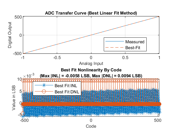
Double click the ADC Testbench block to open the Block Parameters dialog box. Click the Plot DC analysis results button to view the ADC transfer curve, endpoint nonlinearity and best fit nonlinearity.
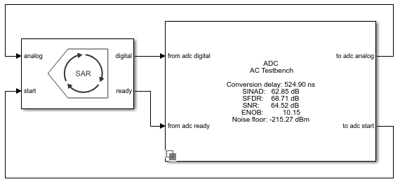
Perform AC Analysis
Double click the ADC Testbench block to open the Block Parameters dialog box. Set the *Measurement option to AC and save the change.
Run the simulation for 9e-3 s. The conversion delay, SINAD, SFDR, SNR, ENOB and Noise floor are displayed on the icon of the ADC Testbench.