Time Delay Beamformer
Time-delay beamformer
Libraries:
      Phased Array System Toolbox / 
      Beamforming
   
Description
The Time Delay Beamformer block performs delay-and-sum beamforming. Plane-wave signals arriving at the array elements are time-aligned and then summed. Time alignment is achieved by transforming the signals into the frequency domain and applying linear phase shifts corresponding to a time delay. The individual signals are then added and converted back to the time domain.
Ports
Input
Input signal, specified as an M-by-N matrix, where M is the number of samples in the data, and N is the number of array elements.
The size of the first dimension of the input matrix can vary to simulate a changing signal length. A size change can occur, for example, in the case of a pulse waveform with variable pulse repetition frequency.
Data Types: double
Complex Number Support: Yes
Beamforming direction, specified as a 2-by-1 real-valued
                            vector. The vector takes the form of
                                [AzimuthAngle;ElevationAngle]. Angle units are in
                            degrees. The azimuth angle must lie between –180° and 180°,
                            inclusive, and the elevation angle must lie between –90° and
                            90°, inclusive. Angles are defined with respect to the local
                            coordinate system of the array.
Dependencies
To enable this port, set the Source of beamforming
direction parameter to Input port.
Data Types: double
Output
Beamformed output, returned as an M-by-1 complex-valued vector. The quantity M is the number of signal samples.
Data Types: double
Complex Number Support: Yes
Beamformed weights, returned as an N-by-1 complex-valued vector. The
                            quantity N is the number of array elements. When the
                                Specify sensor array as parameter is set to
                                Partitioned array or Replicated
                                subarray, N represents the number of
                            subarrays. 
Dependencies
To enable this port, select the Enable weights output checkbox.
Data Types: double
Complex Number Support: Yes
Parameters
Main tab
Signal propagation speed, specified as a real-valued positive scalar. The default
            value of the speed of light is the value returned by
                physconst('LightSpeed'). Units are in meters per second.
Example: 3e8
Data Types: double
Select this parameter to inherit the sample rate from upstream blocks. Otherwise, specify the sample rate using the Sample rate (Hz) parameter.
Data Types: Boolean
Specify the signal sampling rate as a positive scalar. Units are in Hz.
Dependencies
To enable this parameter, clear the Inherit sample rate check box.
Data Types: double
Source of beamforming direction, specified as Property or Input
port. When you set Source of beamforming direction to Property,
you then set the direction using the Beamforming direction
(deg) parameter. When you select Input port,
the direction is determined by the input to the Ang port. 
Beamforming direction, specified as a 2-by-1 real-valued vector taking the form
                [AzimuthAngle;ElevationAngle]. Angle units are in degrees. The
            azimuth angle must lie between –180° and 180°. The elevation angle must lie
            between –90° and 90°. Angles are defined with respect to the local coordinate
            system of the array.
Dependencies
To enable this parameter, set the Source of beamforming
                    direction parameter to Property.
Select this check box to obtain the beamformer weights from the output port,
                W.
Block simulation, specified as Interpreted Execution or
                Code Generation. If you want your block to use the
                MATLAB® interpreter, choose Interpreted Execution. If
            you want your block to run as compiled code, choose Code
                Generation. Compiled code requires time to compile but usually runs
            faster.
Interpreted execution is useful when you are developing and tuning a model. The block
            runs the underlying System object™ in MATLAB. You can change and execute your model quickly. When you are satisfied
            with your results, you can then run the block using Code
                Generation. Long simulations run faster with generated code than in
            interpreted execution. You can run repeated executions without recompiling, but if you
            change any block parameters, then the block automatically recompiles before
            execution.
This table shows how the Simulate using parameter affects the overall simulation behavior.
When the Simulink® model is in Accelerator mode, the block mode specified
            using Simulate using overrides the simulation mode.
Acceleration Modes
| Block Simulation | Simulation Behavior | ||
Normal | Accelerator | Rapid Accelerator | |
Interpreted Execution | The block executes using the MATLAB interpreter. | The block executes using the MATLAB interpreter. | Creates a standalone executable from the model. | 
Code Generation | The block is compiled. | All blocks in the model are compiled. | |
For more information, see Choosing a Simulation Mode (Simulink).
Programmatic Use
Block Parameter:
                    SimulateUsing | 
| Type: enum | 
Values:
                    Interpreted Execution, Code
                        Generation | 
Default:
                    Interpreted Execution | 
Sensor Arrays Tab
Method to specify array, specified as Array (no subarrays)
            or MATLAB expression.
Array (no subarrays)— use the block parameters to specify the array.MATLAB expression— create the array using a MATLAB expression.
MATLAB expression used to create an array, specified as a valid Phased Array System Toolbox array System object.
Example: phased.URA('Size',[5,3])
Dependencies
To enable this parameter, set Specify sensor array as to
                    MATLAB expression.
Element Parameters
Antenna or microphone type, specified as one of the following:
Isotropic AntennaCosine AntennaCustom AntennaOmni MicrophoneCustom Microphone
Specify the operating frequency range of the antenna or microphone element as a 1-by-2
            row vector in the form [LowerBound,UpperBound]. The element has no
            response outside this frequency range. Frequency units are in Hz.
Dependencies
To enable this parameter, set Element type to
                    Isotropic Antenna, Cosine Antenna, or
                    Omni Microphone.
Specify the frequencies at which to set antenna and microphone frequency responses as a 1-by-L row vector of increasing real values. The antenna or microphone element has no response outside the frequency range specified by the minimum and maximum elements of this vector. Frequency units are in Hz.
Dependencies
To enable this parameter, set Element type to Custom
                    Antenna or Custom Microphone. Use
                    Frequency responses (dB) to set the responses at these
                frequencies.
Select this check box to baffle the back response of the element. When back baffled, the responses at all azimuth angles beyond ±90° from broadside are set to zero. The broadside direction is defined as 0° azimuth angle and 0° elevation angle.
Dependencies
To enable this check box, set
                                                  Element type to
                                                  Isotropic Antenna or
                                                  Omni Microphone.
Specify the exponents of the cosine pattern as a nonnegative scalar or a real-valued 1-by-2 matrix of nonnegative values. When Exponent of cosine pattern is a 1-by-2 vector, the first element is the exponent in the azimuth direction and the second element is the exponent in the elevation direction. When you set this parameter to a scalar, both the azimuth direction and elevation direction cosine patterns are raised to the same power.
Dependencies
To enable this parameter, set Element
                                                  type to Cosine
                                                  Antenna.
Frequency response of a custom antenna or custom microphone for the frequencies defined by the Operating frequency vector (Hz) parameter. The dimensions of Frequency responses (dB) must match the dimensions of the vector specified by the Operating frequency vector (Hz) parameter.
Dependencies
 To enable this parameter, set
                                                  Element type to
                                                  Custom Antenna or
                                                  Custom
                                                  Microphone.
Coordinate system of custom antenna pattern, specified
                az-el or phi-theta. When you
            specify az-el, use the Azimuth angles
                (deg) and Elevations angles (deg) parameters to
            specify the coordinates of the pattern points. When you specify
                phi-theta, use the Phi angles (deg)
            and Theta angles (deg) parameters to specify the coordinates of the
            pattern points.
Dependencies
To enable this parameter, set Element type to
                    Custom Antenna.
Specify the azimuth angles at which to calculate the antenna radiation pattern as a 1-by-P row vector. P must be greater than 2. Azimuth angles must lie between –180° and 180°, inclusive, and be in strictly increasing order.
Dependencies
To enable this parameter, set the Element type
                                parameter to Custom Antenna and the
                                        Input Pattern Coordinate System
                                parameter to az-el.
Specify the elevation angles at which to compute the radiation pattern as a 1-by-Q vector. Q must be greater than 2. Angle units are in degrees. Elevation angles must lie between –90° and 90°, inclusive, and be in strictly increasing order.
Dependencies
To enable this parameter, set the Element type
                                parameter to Custom Antenna and the
                                        Input Pattern Coordinate System
                                parameter to az-el.
Phi angles of points at which to specify the antenna radiation pattern, specify as a real-valued 1-by-P row vector. P must be greater than 2. Angle units are in degrees. Phi angles must lie between 0° and 360° and be in strictly increasing order.
Dependencies
To enable this parameter, set the Element type parameter to
                    Custom Antenna and the Input Pattern Coordinate
                    System parameter to phi-theta.
Theta angles of points at which to specify the antenna radiation pattern, specify as a real-valued 1-by-Q row vector. Q must be greater than 2. Angle units are in degrees. Theta angles must lie between 0° and 360° and be in strictly increasing order.
Dependencies
To enable this parameter, set the Element type parameter to
                    Custom Antenna and the Input Pattern Coordinate
                    System parameter to phi-theta.
Magnitude of the combined antenna radiation pattern, specified as a Q-by-P matrix or a Q-by-P-by-L array.
When the Input Pattern Coordinate System parameter is set to
az-el, Q equals the length of the vector specified by the Elevation angles (deg) parameter and P equals the length of the vector specified by the Azimuth angles (deg) parameter.When the Input Pattern Coordinate System parameter is set to
phi-theta, Q equals the length of the vector specified by the Theta Angles (deg) parameter and P equals the length of the vector specified by the Phi Angles (deg) parameter.
The quantity L equals the length of the Operating frequency vector (Hz).
If this parameter is a Q-by-P matrix, the same pattern is applied to all frequencies specified in the Operating frequency vector (Hz) parameter.
If the value is a Q-by-P-by-L array, each Q-by-P page of the array specifies a pattern for the corresponding frequency specified in the Operating frequency vector (Hz) parameter.
Dependencies
To enable this parameter, set Element type to
                    Custom Antenna.
Phase of the combined antenna radiation pattern, specified as a Q-by-P matrix or a Q-by-P-by-L array.
When the Input Pattern Coordinate System parameter is set to
az-el, Q equals the length of the vector specified by the Elevation angles (deg) parameter and P equals the length of the vector specified by the Azimuth angles (deg) parameter.When the Input Pattern Coordinate System parameter is set to
phi-theta, Q equals the length of the vector specified by the Theta Angles (deg) parameter and P equals the length of the vector specified by the Phi Angles (deg) parameter.
The quantity L equals the length of the Operating frequency vector (Hz).
If this parameter is a Q-by-P matrix, the same pattern is applied to all frequencies specified in the Operating frequency vector (Hz) parameter.
If the value is a Q-by-P-by-L array, each Q-by-P page of the array specifies a pattern for the corresponding frequency specified in the Operating frequency vector (
Dependencies
To enable this parameter, set Element type to
                    Custom Antenna.
Select this check box to rotate the antenna element pattern to align with the array normal. When not selected, the element pattern is not rotated.
When the antenna is used in an antenna array and the Input Pattern Coordinate System parameter is az-el, selecting this check box rotates the pattern so that the x-axis of the element coordinate system points along the array normal. Not selecting uses the element pattern without the rotation.
When the antenna is used in an antenna array and Input Pattern Coordinate System is set to phi-theta, selecting this check box rotates the pattern so that the z-axis of the element coordinate system points along the array normal.
Use the parameter in conjunction with the Array normal parameter of the URA and UCA arrays.
Dependencies
To enable this parameter, set Element type to Custom Antenna.
Polar pattern microphone response frequencies, specified as a real scalar, or a real-valued, 1-by-L vector. The response frequencies lie within the frequency range specified by the Operating frequency vector (Hz) vector.
Dependencies
To enable this parameter, set Element type set to
                    Custom Microphone.
Specify the polar pattern response angles, as a 1-by-P vector. The angles are measured from the central pickup axis of the microphone and must be between –180° and 180°, inclusive.
Dependencies
To enable this parameter, set Element type to
                    Custom Microphone.
Specify the magnitude of the custom microphone element polar patterns as an L-by-P matrix. L is the number of frequencies specified in Polar pattern frequencies (Hz). P is the number of angles specified in Polar pattern angles (deg). Each row of the matrix represents the magnitude of the polar pattern measured at the corresponding frequency specified in Polar pattern frequencies (Hz) and all angles specified in Polar pattern angles (deg). The pattern is measured in the azimuth plane. In the azimuth plane, the elevation angle is 0° and the central pickup axis is 0° degrees azimuth and 0° degrees elevation. The polar pattern is symmetric around the central axis. You can construct the microphone response pattern in 3-D space from the polar pattern.
Dependencies
To enable this parameter, set Element type to
                    Custom Microphone.
Array Parameters
Array geometry, specified as one of
ULA— Uniform linear arrayURA— Uniform rectangular arrayUCA— Uniform circular arrayConformal Array— arbitrary element positions
The number of array elements for ULA or UCA arrays, specified as an integer greater than or equal to 2.
Dependencies
To enable this parameter, set Geometry to
                    ULA or UCA.
Spacing between adjacent array elements:
ULA — specify the spacing between two adjacent elements in the array as a positive scalar.
URA — specify the spacing as a positive scalar or a 1-by-2 vector of positive values. If Element spacing (m) is a scalar, the row and column spacings are equal. If Element spacing (m) is a vector, the vector has the form
[SpacingBetweenArrayRows,SpacingBetweenArrayColumns].
Dependencies
To enable this parameter, set Geometry to
                    ULA or URA.
Linear axis direction of ULA, specified as y,
                x, or z. All ULA array
            elements are uniformly spaced along this axis in the local array coordinate
            system.
Dependencies
To enable this parameter, set Geometry to
ULA.This parameter is also enabled when the block only supports ULA arrays.
Dimensions of a URA array, specified as a positive integer or 1-by-2 vector of positive integers.
If Array size is a 1-by-2 vector, the vector has the form
[NumberOfArrayRows,NumberOfArrayColumns].If Array size is an integer, the array has the same number of elements in each row and column.
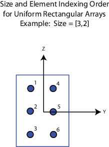
For a URA, array elements are indexed from top to bottom along the
            leftmost array column, and continued to the next columns from left to right. In this
            figure, the Array size value of [3,2] creates an
            array having three rows and two columns.

Dependencies
To enable this parameter, set Geometry to
                    URA.
Lattice of URA element positions, specified as Rectangular
            or Triangular. 
Rectangular— Aligns all the elements in row and column directions.Triangular— Shifts the even-row elements of a rectangular lattice toward the positive row-axis direction. The displacement is one-half the element spacing along the row dimension.
Dependencies
To enable this parameter, set Geometry to
                    URA.
Array normal direction, specified as
                                                  x,
                                                  y, or
                                                  z. 
Elements of planar arrays lie in a plane orthogonal to the selected array normal direction. Element boresight directions point along the array normal direction.
| Array Normal Parameter Value | Element Positions and Boresight Directions | 
|---|---|
x | Array elements lie in the yz-plane. All element boresight vectors point along the x-axis. | 
y | Array elements lie in the zx-plane. All element boresight vectors point along the y-axis. | 
z | Array elements lie in the xy-plane. All element boresight vectors point along the z-axis. | 
Dependencies
To enable this parameter, set
                                                  Geometry to
                                                  URA or
                                                  UCA.
Radius of UCA array, specified as a positive scalar.
Dependencies
To enable this parameter, set Geometry to
                    UCA.
Positions of the elements in a conformal array, specified as a
                3-by-N matrix of real values, where N is the
            number of elements in the conformal array. Each column of this matrix represents the
            position [x;y;z]of an array element in the array local coordinate
            system. The origin of the local coordinate system is (0,0,0). Units
            are in meters.
Dependencies
To enable this parameter set Geometry to Conformal
                    Array.
Data Types: double
Direction of element normal vectors in a conformal array, specified as a 2-by-1 column
            vector or a 2-by-N matrix. N indicates the number
            of elements in the array. If the parameter value is a matrix, each column specifies the
            normal direction of the corresponding element in the form
                [azimuth;elevation] with respect to the local coordinate system.
            The local coordinate system aligns the positive x-axis with the
            direction normal to the conformal array. If the parameter value is a 2-by-1 column
            vector, the same pointing direction is used for all array elements.
You can use the Element positions (m) and Element normals (deg) parameters to represent any arrangement in which pairs of elements differ by certain transformations. The transformations can combine translation, azimuth rotation, and elevation rotation. However, you cannot use transformations that require rotation about the normal direction.
To enable this parameter, set Geometry to Conformal
                Array.
Data Types: double
Specify element tapering as a complex-valued scalar or a complex-valued 1-by-N row vector. In this vector, N represents the number of elements in the array.
Also known as element weights, tapers multiply the array element responses. Tapers modify both amplitude and phase of the response to reduce side lobes or steer the main response axis.
If Taper is a scalar, the same weight is applied to each element. If Taper is a vector, a weight from the vector is applied to the corresponding sensor element. The number of weights must match the number of elements of the array.
Data Types: double
Version History
Introduced in R2014b
See Also
MATLAB Command
You clicked a link that corresponds to this MATLAB command:
Run the command by entering it in the MATLAB Command Window. Web browsers do not support MATLAB commands.
Seleziona un sito web
Seleziona un sito web per visualizzare contenuto tradotto dove disponibile e vedere eventi e offerte locali. In base alla tua area geografica, ti consigliamo di selezionare: .
Puoi anche selezionare un sito web dal seguente elenco:
Come ottenere le migliori prestazioni del sito
Per ottenere le migliori prestazioni del sito, seleziona il sito cinese (in cinese o in inglese). I siti MathWorks per gli altri paesi non sono ottimizzati per essere visitati dalla tua area geografica.
Americhe
- América Latina (Español)
 - Canada (English)
 - United States (English)
 
Europa
- Belgium (English)
 - Denmark (English)
 - Deutschland (Deutsch)
 - España (Español)
 - Finland (English)
 - France (Français)
 - Ireland (English)
 - Italia (Italiano)
 - Luxembourg (English)
 
- Netherlands (English)
 - Norway (English)
 - Österreich (Deutsch)
 - Portugal (English)
 - Sweden (English)
 - Switzerland
 - United Kingdom (English)