GPS Signals
This topic describes the signal specifications of both legacy and modernized Global Positioning System (GPS) signals.
GPS satellites use three distinct frequencies for civilian applications — L1 at 1575.42 MHz, L2 at 1227.60 MHz, and L5 at 1176.45 MHz. GPS uses five distinct civilian signals — coarse acquisition (C/A) code and precision (P) code in the legacy L1 band and L2 band, modernized L1 civil (L1C) code in the L1 band, civil-moderate (CM) code and the civil-long length (CL) code in the L2 band, and in-phase code (I5-code) and quadrature-phase code (Q5-code) in the L5 band. The GPS satellites simultaneously transmit several ranging codes and navigation data. The code-division multiple access (CDMA) spread-spectrum method allows a GPS receiver to distinguish between multiple signals on a given frequency band, such as the legacy and L1C signals transmitted on the L1 band. In this approach, a high-rate pseudo-random number (PRN) sequence spreads the message data transmitted at a low bit rate, and each satellite signal is assigned a unique PRN ID.
To understand how GPS and other global navigation satellite system (GNSS) work following the principles of ranging and trilateration to determine the receiver position, see How GPS Works.
Legacy GPS signals
The original GPS design uses two frequencies: L1 at 1575.42 MHz (10.23 MHz × 154), and L2 at 1227.60 MHz (10.23 MHz × 120). Legacy GPS consists of two ranging codes, C/A-code and P-code, both of which are freely accessible to the public.
Ranging Codes
Legacy GPS design contains these ranging codes:
C/A-code — This ranging code uses the binary phase shift keying (BPSK) modulation technique to transmit on the L1 and L2 frequencies. It consists of a 1023-bit sequence that repeats every millisecond. For more information, see
gnssCACode.This code is available for civilian use without any restrictions.
P-code — This ranging code also uses the BPSK modulation technique to transmit on the L1 and L2 frequencies at a chip rate of 10.23 Mcps. The higher chip rate in P-code contributes to an increase in accuracy when compared to C/A-code. For more information, see
gpsPCode.The P-code is publicly available, but encrypting it with the Y-code to form the P(Y)-code restricts its use to military purposes.
You can generate legacy GPS waveforms by following these steps.
Generate C/A-code using
gnssCACode.XOR the incoming legacy navigation (LNAV) data with the C/A-code. Ensure that the sample rates of LNAV data and C/A-code match.
Map bit 0 to +1 and bit 1 to –1 and then place this waveform on the Q-branch.
Generate P-code using
gpsPCode.XOR the incoming LNAV data with the P-code. Ensure that the sample rates of LNAV data and P-code match.
Map bit 0 to +1/sqrt(2) and bit 1 to –1/sqrt(2) and then place this waveform on the I-branch.
The resultant IQ waveform is the legacy waveform, with the P-code waveform on the I-branch and the C/A-waveform on the Q-branch.

This plot shows the spectrum of GPS signals on the L1-band, displaying C/A-code, P-code, and L1C signals.

Navigation Data
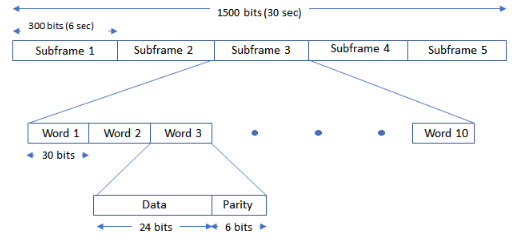
The legacy navigation message (LNAV) is transmitted in 1500 bit-length frames, with each frame consisting of five subframes of 300 bits each. Because the data rate is 50 bps, transmitting each subframe takes 6 seconds, and transmitting each frame takes 30 seconds. Each subframe consists of 10 words with 30 bits (24 data bits and 6 parity bits) in each word. The GPS data contains information regarding the clock and the position of the satellites. This figure shows the frame structure of the LNAV data.
For more details, see the GPS Waveform Generation example.
This table describes the content of each LNAV message subframe.
| Subframe | Word | Description |
|---|---|---|
| 1 | 1–2 | Telemetry word (TLM) and handover word (HOW) |
| 3–10 | Satellite clock and GPS time relationship | |
| 2–3 | 1–2 | TLM and HOW |
| 3–10 | Ephemeris | |
| 4–5 | 1–2 | TLM and HOW |
| 3–10 | Almanac, ionospheric, and UTC data |
Each subframe starts with a TLM and a HOW, both generated by the satellite. The satellite transmits the TLM first, immediately followed by the HOW.
Each TLM word is 30-bit long, occurs every six seconds in the data frame, and is the first word in each subframe. TLM word begins with a preamble, followed by the TLM message, the integrity status flag, one reserved bit, and six parity bits. The TLM message contains the information required by the precise positioning service user and by the control segment.
The HOW is 30-bit long and is the second word in each subframe, immediately following the TLM word. A HOW occurs every 6 seconds in the data frame. The most significant bit (MSB) is transmitted first and the HOW begins with the 17 MSBs of the time-of-week (TOW) count.
This figure shows the TLM and HOW in GPS LNAV data subframe.

Modernized GPS Signals
Modernized GPS civilian signals are characterized by two primary advancements: incorporation of a dataless acquisition aid and application of forward error correction (FEC) coding to the navigation message. The dataless acquisition aid is an additional signal transmitted concurrently with the data signal to facilitate the acquisition of the GPS signal and to improve the power levels. Navigation data has a slow transmission rate, typically at 50 bits per second, and minor disruptions yield disproportionately significant consequences. Hence, implementation of the FEC coding to the navigation message significantly enhances the resilience of the modernized GPS signals.
Modernized Signals
To enhance the quality of service (QoS), modernized GPS introduces new signals: L1C, L2C, M-code, and L5, with L1C, L2C, and L5 freely accessible to the public.
L1C — This signal is open for civilian use and broadcasts on the L1 frequency. It uses the binary offset carrier (BOC) modulation scheme. For details on BOC modulation, see
bocmod.L1C consists of two ranging code components, pilot and data ranging codes, and an overlay code component. The PRN codes are 10,230 chips long and transmitted at 1.023 Mcps, thus repeating every 10 ms. For more information, see
gpsL1CCodes.You can generate an L1C waveform by following these steps.
Generate the data at 100 bits per second and each bit is of 10 millisecond duration, as defined in IS-GPS-800.
L1C uses two types of ranging codes: a ranging code for the data (L1CD code) and a ranging code for the pilot (L1CP code). The chip rate of both the L1CD and L1CP codes is 1.023 mega chips per second with 10 milliseconds in length. Therefore, the number of chips before repeating is 10,230.
Because one 10 millisecond data bit exactly matches the ranging code block size, one data bit is spread with one block of ranging code.
Spread the L1CD code with the user data bits to obtain the data component. The rate of the user data bits is 100 bits per second.
Spread the L1CP code with the overlay code (L1CO code) to obtain the pilot component. The rate of the L1CO code is 100 bits per second.
Modulate the data component by using BOC (1,1).
Modulate the pilot component by using the time-multiplexed BOC (TMBOC) modulation technique.
The final IQ waveform formed is the GPS L1C waveform. For more information on TMBOC modulation, see GPS L1C Waveform Generation.

L2C — This signal is also open for civilian use and broadcasts on the L2 frequency. Unlike the C/A-code, L2C contains two unique PRN code sequences to provide ranging information, the civil-moderate (CM) code and the civil-long (CL) code. These codes are designed to deliver precise ranging information. The CM code is 10,230 chips long and repeats every 20 ms. The CL code is 767,250 chips long and repeats every 1,500 ms. Each signal is transmitted at 511,500 chips per second. However, the signal multiplexes CM and CL together to form a 1.023 Mcps signal.
You can generate an L2C waveform by following these steps.
Generate an L2-CM and an L2-CL code.
XOR the civil navigation (CNAV) data with only the L2-CM code.
Multiplex the XORed CNAV and L2-CM data bit-by-bit with L2-CL code.
Because L2-CM and L2-CL each consists of 511.5 kilo chips per seconds, the multiplexed stream of bits consists of 1.023e6 chips per second
For the multiplexed stream generated in point 4, map bit 0 to +1 and bit 1 to –1. Place this waveform on the Q-branch.
Generate P-code using
gpsPCode.XOR the incoming legacy navigation (LNAV) data with the P-code. Ensure that the sample rates of LNAV data and P-code match.
For the XORed LNAV and P-code data, map bit 0 to +1/sqrt(2) and bit 1 to –1/sqrt(2) and then place this waveform on the I-branch.
The resultant IQ waveform is the baseband GPS L2C waveform.

This plot shows the spectrum of GPS signals on the L2-band, displaying P-code and L2C signals.

M-code — This signal is restricted for military use and is designed to further improve the anti-jamming and secure access of military GPS signals. M-code broadcasts on both the L1 and L2 frequencies. The signal has distinct sideband lobes to improve the signal reception.
L5 — This signal is open for civilian use and broadcasts at the L5 frequency. L5 is designed to meet demanding requirements for safety-of-life (SoL) transportation and other high-performance applications. L5 supports an advanced signal structure that delivers superior performance with a higher transmission power relative to the L1 and L2 signals. This enhancement equates to approximately 3 dB, or a twofold increase in power. An L5 signal transmit two PRN ranging codes, in-phase code (I5-code) and quadrature-phase code (Q5-code). Both codes are 10,230 chips long, transmit at 10.23 Mcps, and repeat after 1 ms. Generation of I5-code and Q5-code is identical, differing only in initial state. For more information, see
gpsL5Codes.You can generate the L5 waveform by following these steps.
Generate GPS L5 CNAV data, as defined in IS-GPS-705 standard.
Generate the ranging code for in-phase (I5-code) and quadrature-phase (Q5-code) components separately, as described in the standard.
Both I5 and Q5-code are at 10.23MHz chip rate and repeat after every 10230 chips. Hence, each code block is of 1 millisecond duration.
The GPS L5 data is at 100 bits per second. XOR each data bit with 10 Newman Huffman code bits for I-branch. This makes the output after this XOR operation to be at 1 kilo baud, meaning every bit will be of 1 millisecond duration, which is equal to one code block of spreading code.
XOR the 1 millisecond bit from the output of step 3 with I5-code block. Map bit 0 to +1/sqrt(2) and bit 1 to -1/sqrt(2) to get the in-phase branch signal component of the final waveform.
Generate 20 bits of Newman Huffman code for Q-branch which is at 1 kilo baud.
XOR each Q5-code block with the Newman Huffman code. Map bit 0 to +1/sqrt(2) and bit 1 to -1/sqrt(2) to get the quadrature-phase branch signal component of the final waveform.
The final IQ waveform formed is the baseband GPS L5 waveform.

This plot shows the spectrum of GPS signals on the L5-band, displaying GPS L5 signal.

Navigation Data
Modernized signals use an enhanced version of the original LNAV message: civil navigation (CNAV) message. CNAV data is more accurate and has higher precision representation. L2C and L5 use the CNAV message structure, whereas L1C uses a different message structure called CNAV-2.
L2C and L5 — The CNAV data transmits continuously in the form of message types. Each message type consists of 300 bits, transmitted at 25 bps for L2C and 50 bps for L5. These bits pass through a rate-half convolutional-encoder to obtain 600 bits from each message type at 50 bps for L2C and 100 bps for L5. Transmitting each message type takes 12 seconds for L2C and 6 seconds for L5. The order in which each message type transmits is completely arbitrary, but is sequenced to provide the optimal user experience. This figure shows the CNAV message structure for L2C. The L5 CNAV message structure is similar to L2C, but it sends data twice as fast at each step.
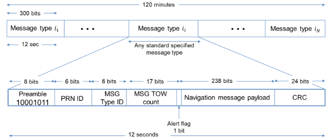
This table describes the content of each CNAV message bit.
Bits Description 1–8 Preamble 9–14 PRN of transmitting satellite 15–20 Message type ID 21–37 Truncated time of week (TOW) count 38 Alert flag 39–276 Navigation message payload 277–300 Cyclic redundancy check L1C — The data rate of CNAV-2 data is 100 bps. Each frame of CNAV-2 data consists of 1800 bits, which is further divided into three subframes. L2C CNAV and L5 CNAV use a dedicated message type for ephemeris, while all CNAV-2 frames include that information.
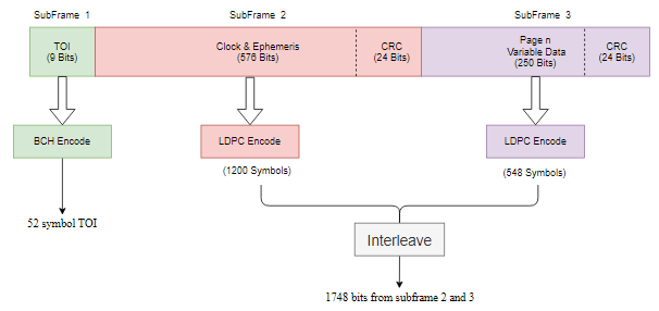
The first subframe consists of 52 bits and contains the time of interval (TOI) information. The actual length of the TOI information is 9 bits, but the Bose Choudhuri Hocquenghem (BCH) encoder encodes these 9 bits and outputs 52 bits.
The second subframe consists of 1200 bits and contains the clock and ephemeris data. The actual length of clock and ephemeris data is 600 bits, but the low-density parity-check code (LDPC) encoder encodes these 600 bits and outputs 1200 bits. The data in the second subframe remains constant over multiple frames until the GPS control segment (CS) updates it.
The third subframe consists of 548 bits and can include almanac data, Earth orientation parameters, differential correction parameters, ionosphere parameters, Universal Coordinated Time (UTC) parameters, text messages, and satellite vehicle configurations. The actual length of the information is 274 bits, but the LDPC encoder encodes these 274 bits and outputs 548 bits. The data in the third subframe changes from frame to frame.
The second and third subframes together constitute 1748 bits. To get one frame of CNAV-2 data, append the 1748 interleaved bits of the second and third subframe to the first subframe. This figure shows the CNAV-2 message structure.
This table describes the content of each CNAV-2 message subframe.
Subframe Bit Count Description Raw Encoded 1 9 52 TOI 2 600 1200 Time correction and ephemeris data 3 274 548 Variable data (almanac, ionospheric information, UTC)
References
[1] IS-GPS-200, Rev: N. NAVSTAR GPS Space Segment/Navigation User Segment Interfaces. Aug 22, 2022; Code Ident: 66RP1.
[2] IS-GPS-800, Rev: J. NAVSTAR GPS Space Segment/User segment L1C Interfaces. Aug 22, 2022; Code Ident: 66RP1.
[3] IS-GPS-705, Rev:J. NAVSTAR GPS Space Segment/User segment L5 Interfaces. Aug 22, 2022.