Automatic Sample-Time Interpolation at Input Port
This example shows how to manage models consisting of both digital communication and RF systems that process signals at different sampling rates. To perform a model simulation where the Nyquist sampling rate of the digital communication signal is less than the inverse of the RF section time step an interpolation filter will be employed. The use of this interpolation filter diminishes the introduction of artificial signal artifacts at the boundaries of the communication and RF systems resulting from the sampling rate differences.
Part 1: Single Signal Entering RF system
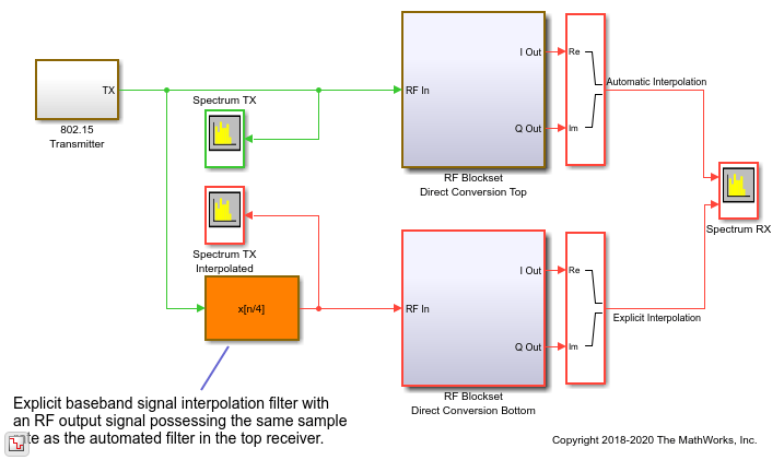
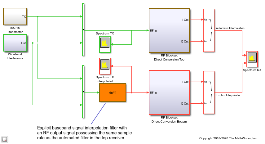
The following model includes a Zigbee® (802.15) baseband signal feeding a direct conversion RF receiver. The ZigBee baseband transmitter is built using blocks from Communications Toolbox™ and DSP System Toolbox™ while the RF receiver is constructed using blocks from the RF Blockset™ Circuit Envelope library.
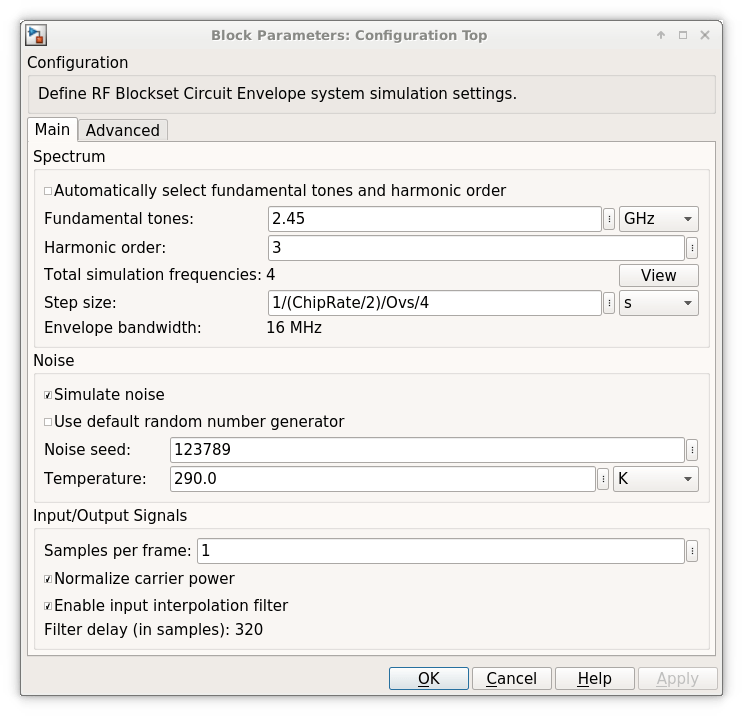
For the RF Blockset Circuit Envelope solver it is recommended to use a simulation time step that is 4 to 8 times smaller than the reciprocal of the input baseband signal sample time. This provides a simulation bandwidth that is sufficient for the RF solver to capture artifacts at the edge of the bandwidth accurately and the physical effects that require additional bandwidth such as spectral regrowth. In general, using an interpolation factor of 4 to 8 increases the simulation bandwidth beyond the Nyquist rate of the baseband signal generated in the transmitter.
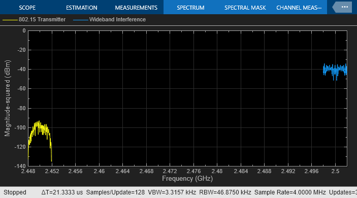
In this model, the two different signal sample rates are:
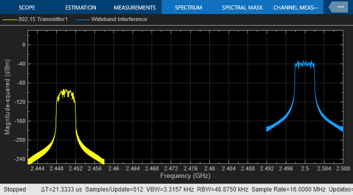
green for the communications baseband signal
red for the RF circuit envelope signal
model = 'simrfV2_sampletime_example';
open_system(model)
sim(model)

% Hide all scopes (see PostLoadFcn Model Callback for more details):
SpTxScopeConf.Visible = false;
SpTXiScopeConf.Visible = false;
SpRxScopeConf.Visible = false;
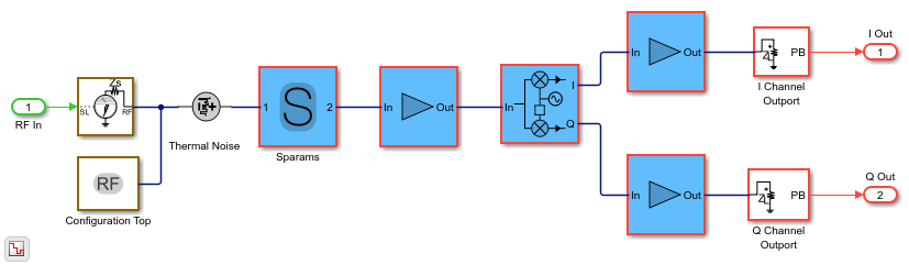
The Top and Bottom RF receiver systems in the model are identical and consist of Pre-LNA filter, followed by an LNA, quadrature demodulator, and another amplification stage. All RF components include typical impairments such as noise, nonlinearity and finite isolation.
open_system([model '/RF Blockset Direct Conversion Top'])
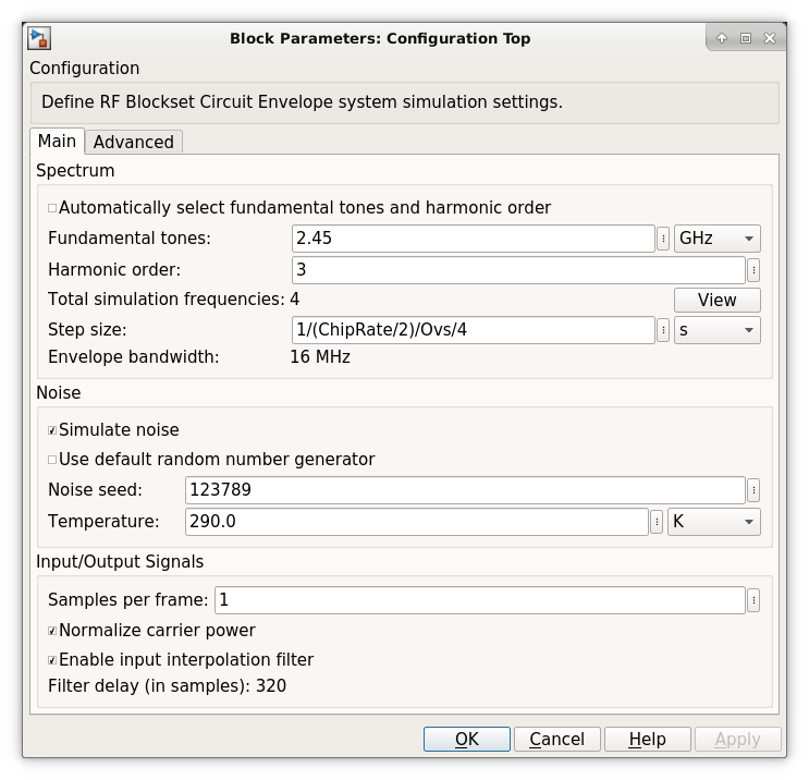
As specified in the Configuration block Mask Parameters dialog box, the simulation is performed with the input interpolation filter enabled for the top receiver,
and disabled for the bottom receiver.
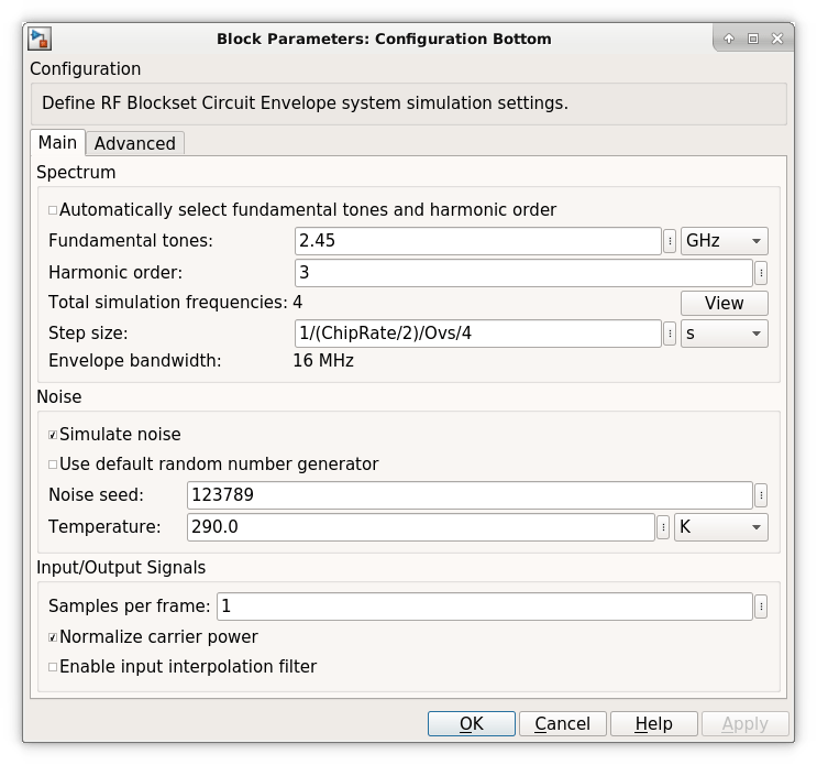
The top RF receiver is fed with a baseband signal possessing a sample rate 4 times slower than the reciprocal of the RF simulation step size set in its Configuration block. The RF Inport block automatically interpolates the input signal at the required RF rate.
The bottom RF receiver is fed with a baseband signal sample rate equaled to the reciprocal of the step size specified in its RF Configuration block. The bottom RF receiver uses an explicit interpolation filter highlighted in orange to upsample the communication baseband signal.
% Show these two scope results:
SpTxScopeConf.Visible = true;
SpTXiScopeConf.Visible = true;
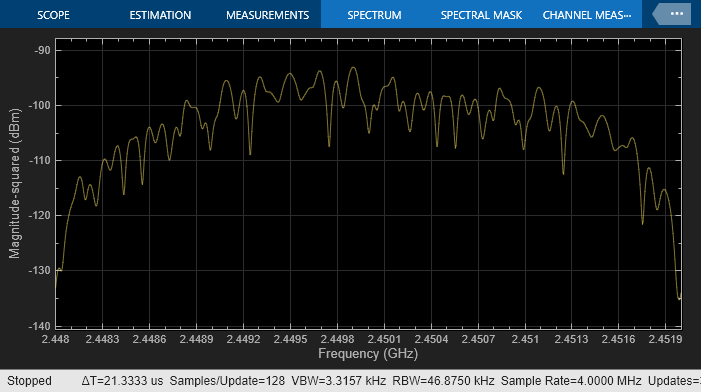
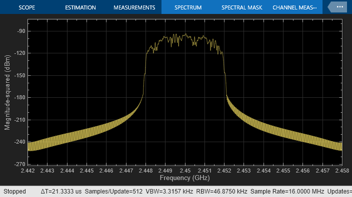
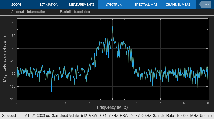
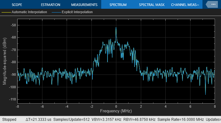
The outputs of both receivers are the same, since both input signals are resampled by interpolation filters to reduce sample rate transition aliasing effects. In the top receiver, the sample rate transition is automatically managed by the circuit envelope Inport block. In the bottom receiver, the sample rate transition is explicitly managed by the addition of the interpolation filter.
% Show this scope result:
SpRxScopeConf.Visible = true;
Using an interpolation filter improves the spectral results of the simulation, but comes at a price: it introduces a delay. Since an FIR filter is used for the interpolation, the delay corresponds to half the number of filter coefficients. In this case, the filter has 640 taps and introduces a delay of 320 time steps at the faster RF sample rate or 80 time steps at the slower baseband communication sample rate. In case of multiple baseband communication signal inputs, it may be necessary to compensate for the delay by aligning all signals entering the RF system.
When an input interpolation filter is enabled in the Configuration block Mask Parameters dialog box, the RF signal delay introduced will be displayed next to the enabling switch.
By default, RF Blockset automatically inserts an interpolation filter and resamples the input signal. You might decide to disable the default option and explicitly insert an interpolation filter if you have:
specific requirements regarding the specifications of the interpolation filter;
multiple input signals requiring different input ports (case described below);
Simulink control signals (e.g. applied to VGA, variable phase shifter or switch blocks) that are intrinsically slower than the RF signal and do not necessitate resampling.
Part 2: Multiple Signals Entering RF System
The automatic interpolation option discussed above can only support a single RF Inport block. When using multiple Inport blocks, the user is required to manually insert interpolation filters before these blocks. The interpolation filters are then adjusted to have all entering communication signals resampled at the rate specified in the RF Configuration block.
While the RF Blockset Inport block can accept a vector of multiple signals each specified at a different carrier frequency, these signals must have the same sample rates. The following model describes two RF systems with multiple inputs centered on different carriers and correctly resampled. The model is like the one in Part 1 of this example, but also includes a wideband interfering signal that is generated using blocks from Communications Toolbox and DSP System Toolbox. The two input signals have the same sample rate and the RF Blockset Configuration block has a Step size that samples the RF signal 4 times faster than the baseband communications signal.
bdclose(model);
model = 'simrfV2_sampletime_example_interf1';
open_system(model);
sim(model);
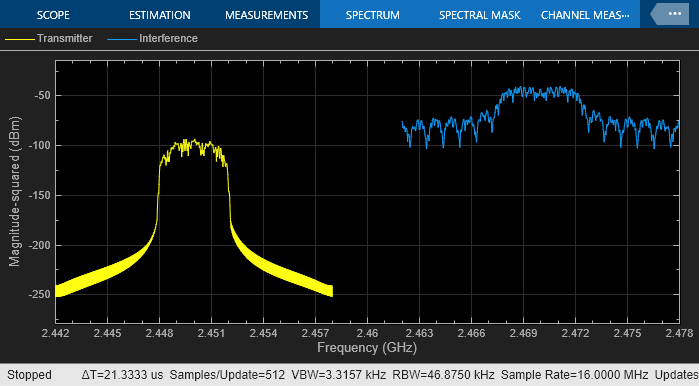
The model is like the one described in Part 1 of this example. The interpolation filter is necessary to avoid aliasing effects due to rate transition.
A more interesting scenario occurs in the following model when the desired and interferer signals have different sample rates. In this model, the desired signal is explicitly interpolated by the filter (highlighted in orange) and then combined with the wideband interferer as a vector.
To avoid the aliasing effect, the slower rate of the desired input signal is interpolated and filtered before combining with the faster rate interfering signal.
bdclose(model);
model = 'simrfV2_sampletime_example_interf2';
open_system(model);
sim(model);

% Hide all scope results (see PostLoadFcn Model Callback for more details):
SpTXComScopeConf.Visible = false;
SpRxSepScopeConf.Visible = false;
SpRxComScopeConf.Visible = false;

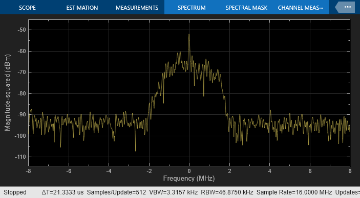
In the top RF receiver, the two signals entering the RF system are centered on different carriers. Note that the sample rate of the signal entering the top RF system is the same as defined in the RF Configuration block. In this case, enabling the automatic input interpolation filter in the RF Configuration block does not introduce any interpolation.
SpRxSepScopeConf.Visible = true;
The last scenario discussed occurs when the two signals entering the RF system are placed on carriers that are relatively close to each other. Since the number of mixing harmonics required for simulation can be large in strongly nonlinear systems, it is recommended to combine the two signals onto one carrier when they are close by.
SpTXComScopeConf.Visible = true;
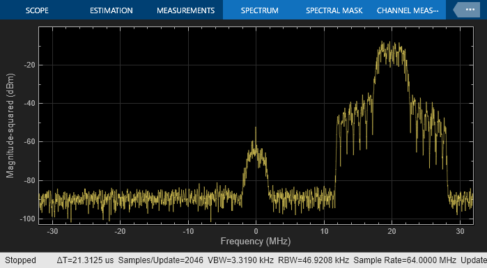
In the bottom receiver, the RF system is fed with the desired signals combined onto a single carrier signal. The combined signal is achieved by multiplying the interfering signal with a complex exponent to shift its operation frequency by 20MHz relative to the frequency of the desired signal. Note that the bandwidth needed to capture both signals when combined on a single carrier is larger than the bandwidth of each individual carrier signal. This is the reason for introducing the interpolation filter highlighted in green before combining the signals.
SpRxComScopeConf.Visible = true;
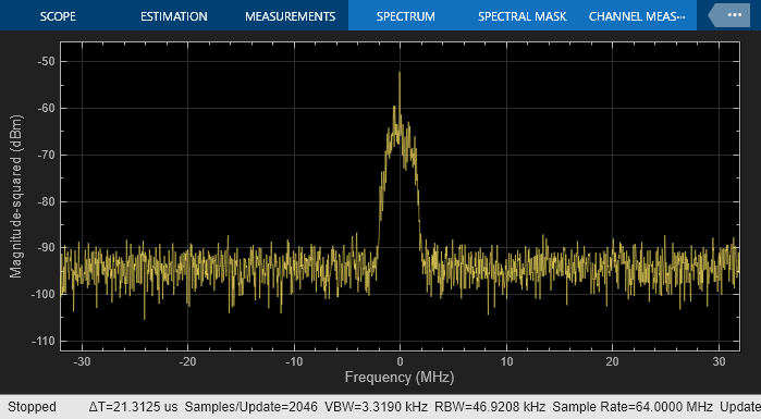
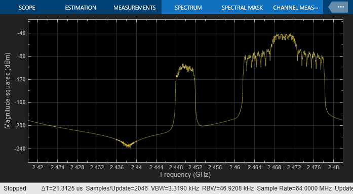
The results of the two RF systems (top and bottom) in the above model show excellent correspondence. The interferer signal is missing from the spectrum in the top RF system since the output port behaves as an ideal filter and only selects the real passband signal centered at DC. The interferer signal is missing from the spectrum in the bottom RF system since the IQ Demodulator includes a channel select filter. To see the effects of the interferer signal, turn off the filter by unchecking the 'Add Channel Select filter' checkbox in the IQ Demodulator block Mask Parameter dialog. The resulting spectrum is
set_param([model '/RF Blockset Direct Conversion Bottom/IQ Demodulator'], ...
    'AddCSFilters', 'off');
sim(model);

% Do not show other scopes and rescale Y axis:
SpTxSepScopeConf.Visible = false;
SpTXComScopeConf.Visible = false;
SpRxSepScopeConf.Visible = false;
SpRxComScopeConf.YLimits = [-103 0];