Rettificatore a ponte full-wave
Questo esempio mostra come dimensionare un condensatore per un carico specifico in un trasformatore che converte 120 V in CA in 12 V in CC. Il sistema è modellato come un trasformatore CA ideale abbinato a un rettificatore a ponte full-wave.
Il trasformatore ha un rapporto di spire di 14 e riduce l'alimentazione a 8,6 volt rms, ovvero 8,6*radice quadrata di (2) = 12 volt picco-picco. Il rettificatore a ponte full-wave combinato con un condensatore converte quindi il segnale in CC. La resistenza rappresenta un carico tipico.
Per una data dimensione del condensatore, all'aumentare della resistenza del carico, aumenta l'ondulazione della tensione CC. Il modello può inoltre essere utilizzato per pilotare un circuito applicativo per valutare l'effetto dell'ondulazione.
Modello

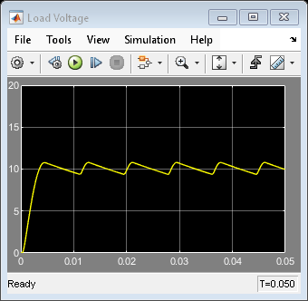
Risultati di simulazione dagli Scope
Risultati di simulazione da Simscape Logging
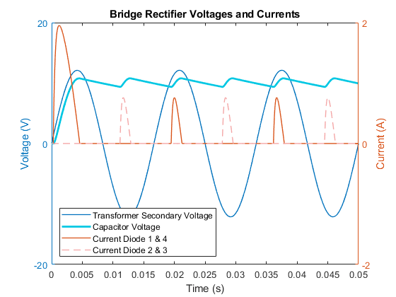
Il grafico "Tensioni e correnti del raddrizzatore a ponte" mostra come la tensione CA viene convertita in tensione CC. La linea blu scuro rappresenta la tensione CA sul lato sorgente del ponte. Il flusso di corrente attraverso il ponte di diodi può avvenire tramite due percorsi. I picchi alternati attraverso i diodi 1&4 e i diodi 2&3 mostrano che il flusso di corrente che raggiunge il condensatore scorre nella stessa direzione anche se cambia la polarità della tensione. L'ondulazione della tensione di carico corrisponde alla carica e alla scarica del condensatore.