Integrate Low Pass Filter Python Code into Simulink Using Python Code Block
This example shows how to integrate your native Python® code into Simulink® using the Python Code block. Use the Python Code block to directly import or write Python code into the block dialog.
In this example, native Python code defining the implementation of a first order low pass filter is integrated into Simulink using the Python Code block. The filter is defined in the Laplace domain by the equation,
where is the cutoff frequency.
This filter can be represented in time domain using Tustin Bilinear transform as,
,
,
where:
and are the filter outputs at the current and previous time steps.
and are the filter inputs at the current and previous time steps.
is the sample time.
Define Filter Using Native Python Code
Consider the following Python code file firstOrderLowPassFilter.py that defines the implementation of the low pass filter using a Python class FirstOrderLowPassFilter. The class contains four properties: cutoff_frequency, sample_time, previous_input, and previous_output. The class constructor takes in cutoff_frequency and sample_time as inputs and initializes previous_input and previous_output as 0. The computeFilterOutput method takes in the signal values through input_value and performs the computation for filtering the signal based on the specified cutoff frequency and sample time.
class FirstOrderLowPassFilter:
    def __init__(self, cutoff_frequency, sample_time):
        self.cutoff_frequency = cutoff_frequency
        self.sample_time = sample_time
        self.previous_input = 0.0
        self.previous_output = 0.0

    def computeFilterOutput(self, input_value):
        alpha = (3.14 * self.cutoff_frequency * self.sample_time)

        output = ((1 - alpha) / (1 + alpha)) * self.previous_output + ((alpha) / (1 + alpha)) * (input_value + self.previous_input)

        self.previous_output = output
        self.previous_input = input_value

        return output
Integrate Filter Into Simulink Using Python Code Block
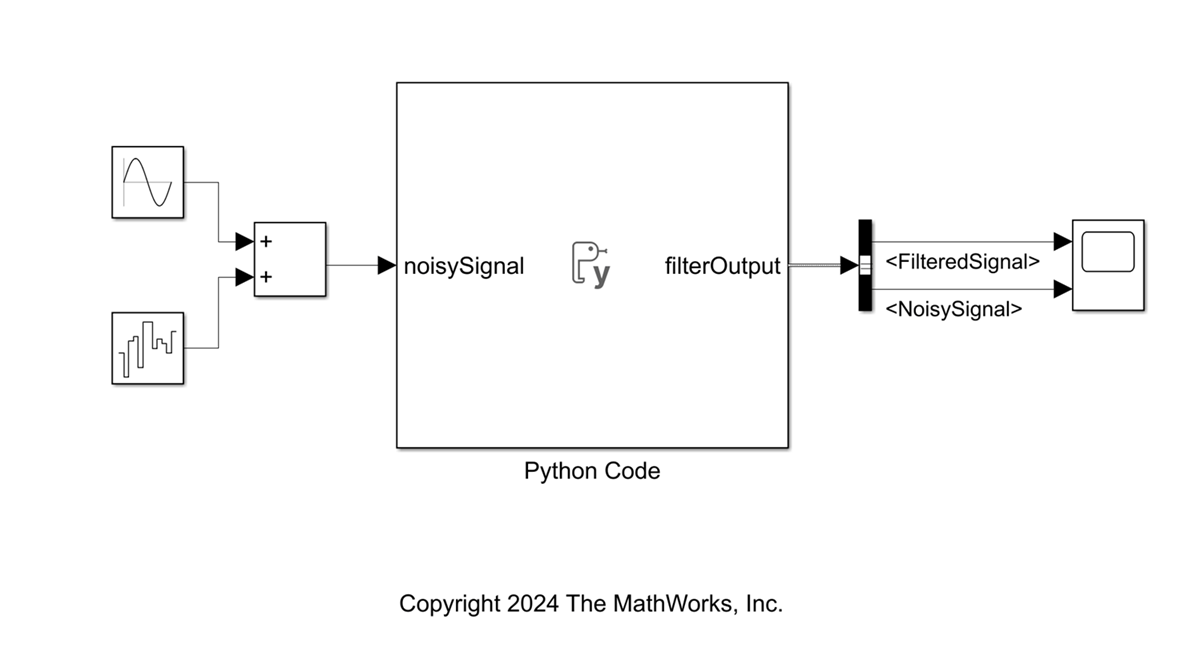
Open simulationFilterModel.slx Simulink model that contains the Python code block. The block integrates the Python implementation of the low-pass filter into Simulink and outputs filtered signal at every time step. The block accepts a scalar input and outputs a bus signal containing two elements, the filtered signal and the noisy signal. The block dialog enables you to specify the cutoff frequency and sample time for the filter.
open_system("simulationFilterModel");Double click on the Python Code block or select the block and press CTRL + U to open the block dialog. The block dialog contains three code panes, Initialize, Output, and Terminate. These panes enable you to specify Python Code for different simulation stages. The Ports and Parameters table enables you to specify the block interface, parameters, and persistent Python objects for storing states.
Run the createBus.m script to initialize the bus object for the block output.
createBus;
Specify the interfaces for this Python code block using the Add button of the Ports and Parameters table. Configure the block to take in a scalar input of type double and output a bus type defined as filterOutput in the script. Specify cutoffFrequency and filterSampleTime as parameters for the block. Use the PythonObject type to specify a Persistent variable to store the filter object and retain states between simulation time steps.

Use the Initialize pane to import the Python code from firstOrderLowPassFilter.py file and create a filter object with the cutoff frequency and sample time parameters.
from firstOrderLowPassFiler import FirstOrderLowPassFilter
filterObject = FirstOrderLowPassFilter(cutoff_frequency=cutoffFrequency, sample_time=filterSampleTime)
Use the Output pane to specify the action for each time step. Specify the filterObject to calculate filtered signal based on the current input. Define a Python dictionary with keys matching the bus element names to define the bus output for the block.
filteredSignal = filterObject.computeFilterOutput(noisySignal)

filterOutput = {
    'FilteredSignal': filteredSignal,
    'NoisySignal': noisySignal
}
Click Apply and OK button on the block dialog. Doing so close the block dialog.
Double click on the Python Code block to open the block mask with the parameter fields. Specify the desired sample time and cutoff frequency for the filter.

Compile the Simulink model.
Simulate Model
You can now simulate the model with the Python Code block. Input a noisy signal and observe the filtered signal output from the filter block based on the specified sample time and cutoff frequency for the block.
model = 'simulationFilterModel';
simData = sim(model);

figure(1);
plot(simData.yout{2}.Values,'--r','LineWidth',1)
hold on
plot(simData.yout{1}.Values,'g','LineWidth',2)
grid minor
xlabel('Time')
ylabel('Signal Value')
title('Filter Simulation')
legend('Noisy Signal', 'Filtered Signal')
