Main Content

External Interrupt

Trigger the downstream function-call subsystem from an Interrupt Service Routine

Add-On Required: This feature requires the Simulink Support Package for Arduino Hardware add-on.

  • External Interrupt block

Libraries:
Simulink Support Package for Arduino Hardware / Common

Description

The External Interrupt block configures Simulink® to treat the downstream Function-Call Subsystem, connected to the output port of the block, as an Interrupt Service Routine (ISR). ISR is a section of code that the CPU triggers when the selected interrupt occurs at the selected pin of the hardware.

During simulations, you can provide an input to the block by connecting a Source block from the Simulink library to the input port of the block. If the input provided to the block is boolean true, the block triggers the downstream function-call subsystem. If no input is provided, the block triggers the downstream function-call subsystem until the simulation continues to run. During code generation, any simulation block that is connected to the input port of the block is ignored and has no effect on the generated code.

Note

  • We recommend that you use the External Interrupt block only in the parent model of a model hierarchy. For more information, refer to Model References.

  • The External Interrupt block does not support the Arduino® Nano 33 BLE Sense board currently.

Ports

Input

expand all

During simulations, you can simulate an input to the block by connecting a Source block from the Simulink library to the SimIRQ port. If the input provided to the block is boolean true, the block triggers the downstream function-call subsystem. If no input is provided, the block triggers the downstream function-call subsystem until the simulation continues to run. During code generation, any block that is connected to this port is ignored and has no effect on the generated code.

Dependencies

The SimIRQ port is available only when you select the Add simulation input port parameter in the block parameters dialog box.

Data Types: Boolean

Output

expand all

The IRQ port connects the downstream Function-Call Subsystem to be triggered when the selected interrupt occurs.

Parameters

expand all

Specify the digital input pin number on the hardware to be used to generate external interrupts. The pins that can be used for interrupts are different for different Arduino hardware. For information about the pins supported on Arduino for interrupts, see Pins With Interrupts.

Click View pin map to open the Arduino Pin Mapping table.

To know how to assign pins for the block, see Pin Mapping for Arduino Timer Independent Blocks.

  • on – The selected hardware pin is set to logical high when no input is connected to the pin.

  • off – The selected hardware pin is left floating when no input is connected to the pin.

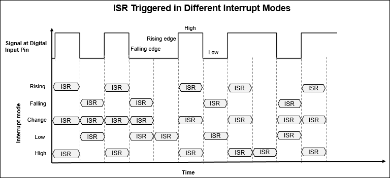
Select a Mode to specify which of these transitions on the selected pin triggers the downstream function call.

ModeInterrupt Trigger Condition
LOWThe pin is low.
CHANGEThe pin value changes.
RISINGThe pin value goes from low to high.
FALLINGThe pin value goes from high to low.
HIGHThe pin value is high.

This figure shows how the block executes the downstream function call as the pin value changes in different interrupt modes.

When you select the Add simulation input port parameter, the SimIRQ input port becomes available. To provide an input to the block during simulation, connect a Source block to the SimIRQ input port. During code generation, any block connected to the port is ignored and has no effect on the generated code.

Tips

  • Using serial blocks inside the function subsystem is not recommended. Interrupts triggered by the serial blocks to transfer data inside the ISR result in nested interrupts, which in turn may cause data loss to occur.

  • Using the same Arduino board to provide an input to the External Interrupt block may result in a racing condition between the input signal and the ISR. Use another Arduino board instead.

Version History

Introduced in R2019a
Go to top of page