Define Bus Properties at Component Interfaces
To assign or validate a bus at a subsystem or model interface, define the bus with one or
more In Bus Element or Out Bus Element blocks.
Optionally, use a Simulink.Bus object.
In Bus Element and Out Bus Element blocks let you define a bus with or without a bus object. You can add elements to the port with or without adding blocks to the block diagram.
Simulink.Busobjects let you reuse and share a bus definition. To simulate a model that uses bus objects, you must load the bus objects by using projects, data dictionaries, model callbacks, or other strategies.
Defining the properties of elements at a component interface is useful when you create a file for reuse. The interface definition determines the input that a subsystem or model supports. The hierarchy and properties of the input bus must match the definition at the corresponding port.
Define Bus Properties at Bus Element Port
To define a bus element port without Simulink.Bus objects,
individually specify the properties of the bus and bus elements.
Suppose you want to specify the new port using this bus definition.
InBus— Top-level bus that contains elements namedStepandNestedBusStep— Step signal with a minimum value of0and a maximum value of1NestedBus— Nested bus that contains elements namedChirpandSineChirp— Chirp signal with a minimum value of-1and a maximum value of1Sine— Sine wave signal with a minimum value of-1and a maximum value of1
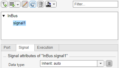
In a blank model or subsystem, add an In Bus Element or Out Bus Element block. This example adds an In Bus Element block.
![]()
To rename the element that the block represents, in the block label, double-click
signal1. Then, replace signal1 with
Step.

Open the Property Inspector. Then, select the In Bus Element block. Alternatively, double-click the block to open a dialog box.
In the Property Inspector or dialog box, select the top-level bus named
InBus. Then, click the ![]() button arrow, and select Add element
without block.
button arrow, and select Add element
without block.

The new element is nested under the previously selected element. The block diagram is unchanged.

The new element name is gray and italicized to indicate that an In Bus Element block does not represent the element directly.
Double-click the new element name. Then, enter
NestedBus.

To add an element to the nested bus, select NestedBus. Then,
click the ![]() button arrow, and select Add element
without block.
button arrow, and select Add element
without block.

To add another bus element, select NestedBus. Then, click the ![]() button arrow, and select Add element
without block.
button arrow, and select Add element
without block.

To rename the bus elements from signal and
signal2 to Chirp and
Sine, respectively, double-click each new element name and
enter the new name.

By adding elements without adding blocks, you can define the entire bus hierarchy
with only one In Bus Element block and without a
Simulink.Bus object.
Tip
When you want to add many elements without blocks, using the
Simulink.Bus.addElementToPort function can be quicker
than using the dialog box. For an example, see Programmatically Create Bus Element Ports.
To toggle the display of the port, signal, and execution attributes, click ![]() . Then, specify the attributes as needed.
. Then, specify the attributes as needed.

Before R2025a: To specify attributes, pause on the name of
a bus, signal, or message. Then, click ![]() for signal attributes or
for signal attributes or
![]() for execution attributes. Alternatively, when
available, click an attribute summary.
for execution attributes. Alternatively, when
available, click an attribute summary.
For example, specify the minimum and maximum values for the signals.

When you specify attributes, an attribute summary appears next to the element name. To further edit the attributes, click the attribute summary next to an element name.
For more examples and information, see In Bus Element and Out Bus Element.
Specify Reusable Bus Properties at Bus Element Port
To define a bus element port with Simulink.Bus objects, specify a
bus object as the data type of the top-level bus at the port.
Suppose you want to specify the new port using this bus object definition:
elems(1) = Simulink.BusElement;
elems(1).Name = 'Chirp';
elems(1).Min = -1;
elems(1).Max = 1;
elems(2) = Simulink.BusElement;
elems(2).Name = 'Sine';
elems(2).Min = -1;
elems(2).Max = 1;
Sinusoidal = Simulink.Bus;
Sinusoidal.Elements = elems;
clear elems

elems(1) = Simulink.BusElement;
elems(1).Name = 'Step';
elems(1).Min = 0;
elems(1).Max = 1;
elems(2) = Simulink.BusElement;
elems(2).Name = 'NestedBus';
elems(2).DataType = 'Bus: Sinusoidal';
TopBus = Simulink.Bus;
TopBus.Elements = elems;
clear elems
In a blank model or subsystem, add an In Bus Element or Out Bus Element block. This example adds an In Bus Element block.
![]()
Open the Property Inspector. Then, select the port block. Alternatively, double-click the block to open a dialog box.
To toggle the display of the port, signal, and execution attributes, click ![]() .
.
Before R2025a: To specify attributes, pause on the name of
a bus, signal, or message. Then, click ![]() for signal attributes or
for signal attributes or
![]() for execution attributes. Alternatively, when
available, click an attribute summary.
for execution attributes. Alternatively, when
available, click an attribute summary.
Select the top-level bus. Then, set Data type to
Bus: TopBus.
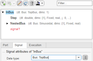
The bus hierarchy updates to reflect the specified bus object. An attribute summary appears next to each bus and bus element defined by the bus object.
The Property Inspector displays signal1 as red and
italicized with no attribute summary. The In Bus Element block
selects this element from the port, but this element is missing from the specified
bus object. The bus hierarchy must match between the incoming bus and the specified
bus object. When an element name is red and italicized, pause on the name to display
a message that describes the problem. In this example, an element from the incoming
bus is missing from the bus object. The opposite can also be true. An element from
the bus object can be missing from the incoming bus.
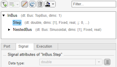
In the block diagram, delete signal1 from the second field of
the block label. Then, select an element from the list. For example, select
Step.

The bus hierarchy updates to no longer include signal1.
For more information about bus objects, see Define Bus Properties for Reuse.