Use Simulink.Signal Objects to Specify and Control Signal
Attributes
A Simulink.Signal object enables you to
assign or validate the attributes of a signal or discrete state, such as its data type,
numeric type, dimensions, and so on.
Using Signal Objects to Assign or Validate Signal Attributes
You can use signal objects to assign or validate signal attributes. The same techniques work with discrete states also. To use a signal object to assign or validate signal attribute values:
Create a
Simulink.Signalobject that has the same name as the signal to which you want to assign attributes or whose attributes you want to validate.Open the Model Explorer.
In the Model Hierarchy pane, select either the Base workspace or Model workspace node, depending on the context you want for the signal object. If you create the signal object in a model workspace, you must set the Storage class parameter to
Auto.Select Add > Simulink Signal.
Set the properties of the object that correspond to the attributes left unspecified by the signal source, or that correspond to the attributes you want to validate.
Enable explicit or implicit signal resolution:
Explicit resolution: In the Signal Properties dialog box for the signal, enable Signal name must resolve to Simulink signal object. This is the preferred technique. See Explicit and Implicit Symbol Resolution for more information.
When you use this technique, set Configuration Parameters > Diagnostics > Data Validity > Signal resolution to a value other than
None. To use only explicit resolution (a best practice), set the parameter toExplicit only.Implicit resolution: Set the Configuration Parameters > Diagnostics > Data Validity > Signal resolution option for the model to
Explicit and implicitorExplicit and warn implicit. Explicit resolution is the preferred technique.
Assign the signal object to a workspace variable.
Associate the signal object with the source signal.
Give the signal the same name as the workspace variable that references the signal object.
You can use a variety of techniques to associate a signal object with a signal. For examples, see Use Signal Objects to Initialize Signals and Discrete States, Using Signal Objects to Tune Initial Values, and Organize Parameter Data into a Structure by Using Struct Storage Class (Embedded Coder).
Validation
The result when a signal does not match a signal object can depend on several factors. Simulink® software can validate a signal property when you update the diagram, while you run a simulation, or both. When and how validation occurs can depend on internal rules that are subject to change, and sometimes on configuration parameter settings.
Not all signal validation compares signal source attributes with signal object properties. For example, if you specify Minimum and Maximum signal values using a signal object, the signal source must specify the same values as the signal object (or inherit the values from the object) but such validation relates only to agreement between the source and the object, not to enforcement of the minimum and maximum values during simulation.
If the value of Configuration Parameters > Diagnostics
> Data Validity > Simulation range checking is
none (the default), Simulink does not enforce any minimum and maximum signal values during
simulation, even though a signal object provided or validated them. To enforce
minimum and maximum signal values during simulation, set Simulation range checking to warning or
error. See Specify Signal Ranges and Model Configuration Parameters: Data Validity for
more information.
Multiple Signal Objects
You can associate a given signal object with more than one
signal if the storage class of the signal object is Auto or
Reusable. If the storage class is Auto and
you clear optimizations such as Signal storage reuse so that
the generated code allocates memory for all of the associated signals, the signals
each appear as a uniquely named field of the global structure that contains signal
and state data. If the storage class of the object is other than
Auto or Reusable, you can associate the
signal object with no more than one signal.
You can associate a given signal with no more than one signal object. The signal can refer to the signal object more than once, but every reference must resolve to exactly the same signal object. Referencing two different signal objects that have exactly the same properties causes a compile-time error.
A compile-time error occurs if a model associates more than one signal object with any signal. To prevent the error, decide which object you want the signal to use, then delete or reconfigure all references to any other signal objects, so that all remaining references resolve to the chosen signal object. See Highlight Signal Sources and Destinations for a description of techniques that you can use to trace the full extent of a signal.
Signal Specification Block: An Alternative to Simulink.Signal
You can use a Signal Specification block rather
than a Simulink.Signal object to assign properties left unspecified
by a signal source. Each technique has advantages and disadvantages:
Using a signal object simplifies the model and allows you to change signal property values without editing the model, but does not show signal property values directly in the block diagram.
Using a Signal Specification block displays signal property values directly in the block diagram, but complicates the model and requires editing it to change signal property values.
The following two models illustrate the respective advantages of the two ways of assigning attributes to a signal.
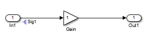
In the first example, the signal object named Sig1 specifies
the sample time and data type of the signal emitted by input port
In1.
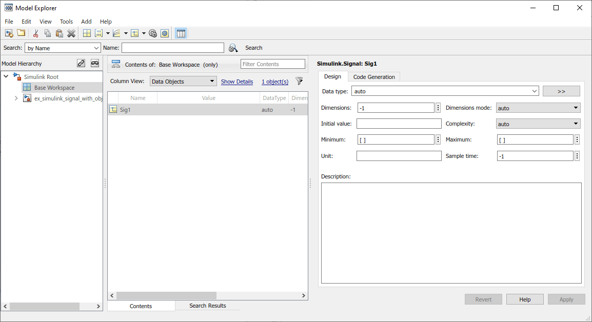
To determine the properties of the Sig1 signal, you can view
the signal object in the Model Explorer. In this model, the sample time is
-1 and the data type is auto.
Using a signal object to specify the sample time and data type properties of
signal Sig1 allows you to change the sample time or data type
without having to edit the model. For example, you could use the Model Explorer, the
MATLAB® command line, or a MATLAB program to change these properties.
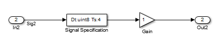
The second example uses a Signal Specification block specifies the
sample time and data type of the signal emitted by input port
In2. The Signal Specification block displays the
data type and signal sample time properties right in the diagram, which in this case
are uint8 and 4, respectively.
Bus Support
Using Bus Objects as the Data Type
Simulink.Signal supports nonvirtual buses as the output data
type.
If you set the Data type of the signal object to be a bus object, then you cannot associate the signal object with a nonbus signal.
Using Structures for the Initial Value
If you use a bus object as the data type, set Initial
value to 0 or a MATLAB structure that matches the bus object.
The structure you specify must contain a value for every element of the bus represented by the bus object.
You can use the Simulink.Bus.createMATLABStruct to create a full structure that
corresponds to a bus.
You can use Simulink.Bus.createObject to
create a bus object from a MATLAB structure.